Slot insulating paper

a slot insulating paper and slot technology, applied in the field of slot insulating paper, can solve the problems of deterioration of the workability of inserting the slot insulating paper into the slot, hard deformation of the breakage resistance portion, and partially increased resistance to breakage, so as to reduce the cost of the slot insulating paper

Active Publication Date: 2018-10-30
TOYOTA JIDOSHA KK
View PDF15 Cites 2 Cited by
  • Summary
  • Abstract
  • Description
  • Claims
  • Application Information

AI Technical Summary

Benefits of technology

[0007]A slot insulating paper is required not to break in order to ensure electrical insulation; however, easiness to break depends on a location inside a slot. For example, a portion that the coil strongly contacts is easy to break. However, each of the slot insulating papers respectively described in JP 2008-178197 A and JP 2010-115040 A is uniform as a whole, and does not show a configuration that resistance against breakage is partially increased. In JP 4-210744 A and JP 2011-200046 A, breakage of a portion of the slot insulating paper is prevented by folding and doubling the portion of the slot insulating paper; however, a working process for folding is required. In addition, workability of work for inserting the slot insulating paper into a slot may deteriorate due to reaction force that the folded portion attempts to return.
[0008]The invention improves breakage resistance of a desired portion in a slot insulating paper.

Problems solved by technology

However, each of the slot insulating papers respectively described in JP 2008-178197 A and JP 2010-115040 A is uniform as a whole, and does not show a configuration that resistance against breakage is partially increased.
In addition, workability of work for inserting the slot insulating paper into a slot may deteriorate due to reaction force that the folded portion attempts to return.
With the high stiffness layer, the breakage resistance portion becomes hard to deform.

Method used


Image

  • Slot insulating paper
  • Slot insulating paper
  • Slot insulating paper

Examples


Embodiment Construction

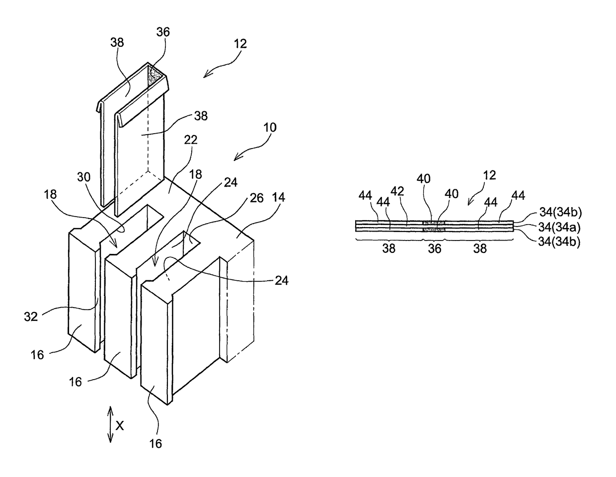
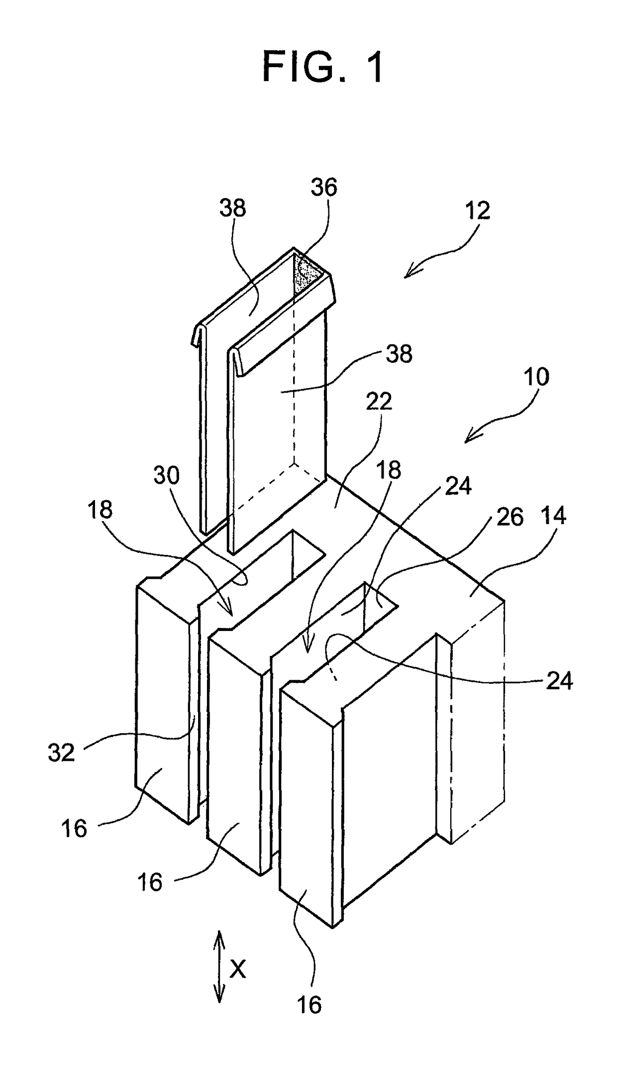
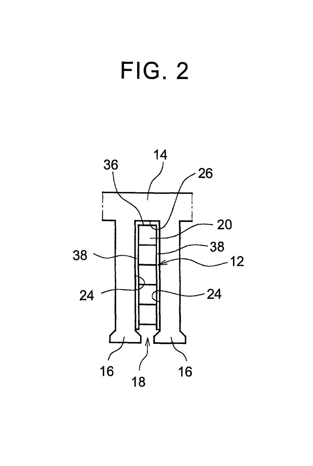
[0026]Hereinafter, an embodiment of the invention will be described with reference to the accompanying drawings. Between relatively movable two portions of an electric motor, generally, one of the two portions is fixed, and the other one of the two portions is movable. The movable portion is of a type that rotates around one axis, and this electric motor is of a rotary type. In the rotary-type electric motor, the movable portion is called rotor, and the fixed portion is called stator. In addition, there is also known a so-called linear electric motor in which the movable portion moves along a straight line or a free-form curve. In the linear electric motor, the movable portion is called slider, or the like, and the fixed portion is called stator. Hereinafter, high stiffness portion refers to a reinforced portion, high stiffness layer refers to a reinforced layer, ordinary portion refers to a non-reinforced portion, and ordinary layer refers to a non-reinforced layer.

[0027]FIG. 1 sho...


PUM

PropertyMeasurementUnit
breakage resistanceaaaaaaaaaa
resistanceaaaaaaaaaa
thicknessaaaaaaaaaa

Abstract

A slot insulating paper (12) is arranged in a slot (18) of a core (10) of an electric motor or generator. In a state where the slot insulating paper (12) is spread in a sheet shape, a region (high stiffness portion (36)) that is part of the slot insulating paper (12) is a breakage resistance portion having a higher resistance against breakage than the other region (ordinary portion (38)). The slot insulating paper (12) may be formed by laminating a plurality of insulating layers. In the breakage resistance portion, for example, at least one of the laminated insulating layers is a high stiffness layer formed of a high stiffness material. Thus, the breakage resistance portion is formed to have a high stiffness. With a high stiffness, it is possible to improve breakage resistance.

Description

BACKGROUND OF THE INVENTION[0001]1. Field of the Invention[0002]The invention relates to a slot insulating paper arranged in a slot of a core of an electric motor or generator.[0003]2. Description of Related Art[0004]An electric motor is an electrical device that includes two portions and that causes relative motion between the two portions by causing interaction of a shifting magnetic field, formed by supplying electric power to one of the portions, with the other one of the portions. The portion that forms the shifting magnetic field includes a core and coils. The core has a yoke extending in a direction in which the magnetic field shifts and teeth protruding from the yoke and arranged in the magnetic field shifting direction. A portion between any adjacent two of the teeth is called slot. The coils are formed such that conductive wires are wound around the teeth, with the result that the coils are partially located inside the slots.[0005]In contrast to the electric motor that con...

Claims


Application Information

Patent Timeline
Patent Type & Authority Patents(United States)
IPC IPC(8): H02K3/34H01B3/52
CPCH01B3/52H02K3/345
Inventor HATTORI, HIROYUKI
Owner TOYOTA JIDOSHA KK
Why Eureka
Try Eureka