Video encoding device, video encoding method, and program

a video encoding and video encoding technology, applied in the field of video encoding devices, can solve the problems of not revealing a technique for distributing the load in the video encoding device, and achieve the effects of distributing the processing load, preventing a decrease in image quality, and reducing image quality

Active Publication Date: 2018-10-30
NEC CORP
View PDF19 Cites 33 Cited by
  • Summary
  • Abstract
  • Description
  • Claims
  • Application Information

AI Technical Summary

Benefits of technology

[0050]Patent Literature (PTL) 1 describes a video encoding device including a first encoding part and a second encoding part. However, PTL 1 does not disclose a technique for distributing the load in the video encoding device. PTL 2 and PTL 3 each describe a video encoding device that divides one screen, inputs each divided screen (each of a plurality of screens obtained by division) to a corresponding encoder, and integrates bitstreams generated by the respective encoders. An encoder described in PTL 2 encodes macroblocks near a dividing line as intra blocks, and reduces the number of intra blocks as the distance from the dividing line increases. An encoder described in PTL 3 reconstructs images of a non-overlapping area and an overlapping area on the decoding side. Neither PTL 2 nor PTL 3, however, discloses a technique for distributing the load in the video encoding device.
[0139]According to the present invention, the computational load of the video encoding process is distributed between the first video encoding means and the second video encoding means, so that the concentration of the load can be avoided. Moreover, a decrease in image quality in a dividing line between divided screens can be prevented.

Problems solved by technology

However, PTL 1 does not disclose a technique for distributing the load in the video encoding device.

Method used


Image

  • Video encoding device, video encoding method, and program
  • Video encoding device, video encoding method, and program
  • Video encoding device, video encoding method, and program

Examples


Embodiment Construction

[0177]The following describes an exemplary embodiment of the present invention with reference to drawings.

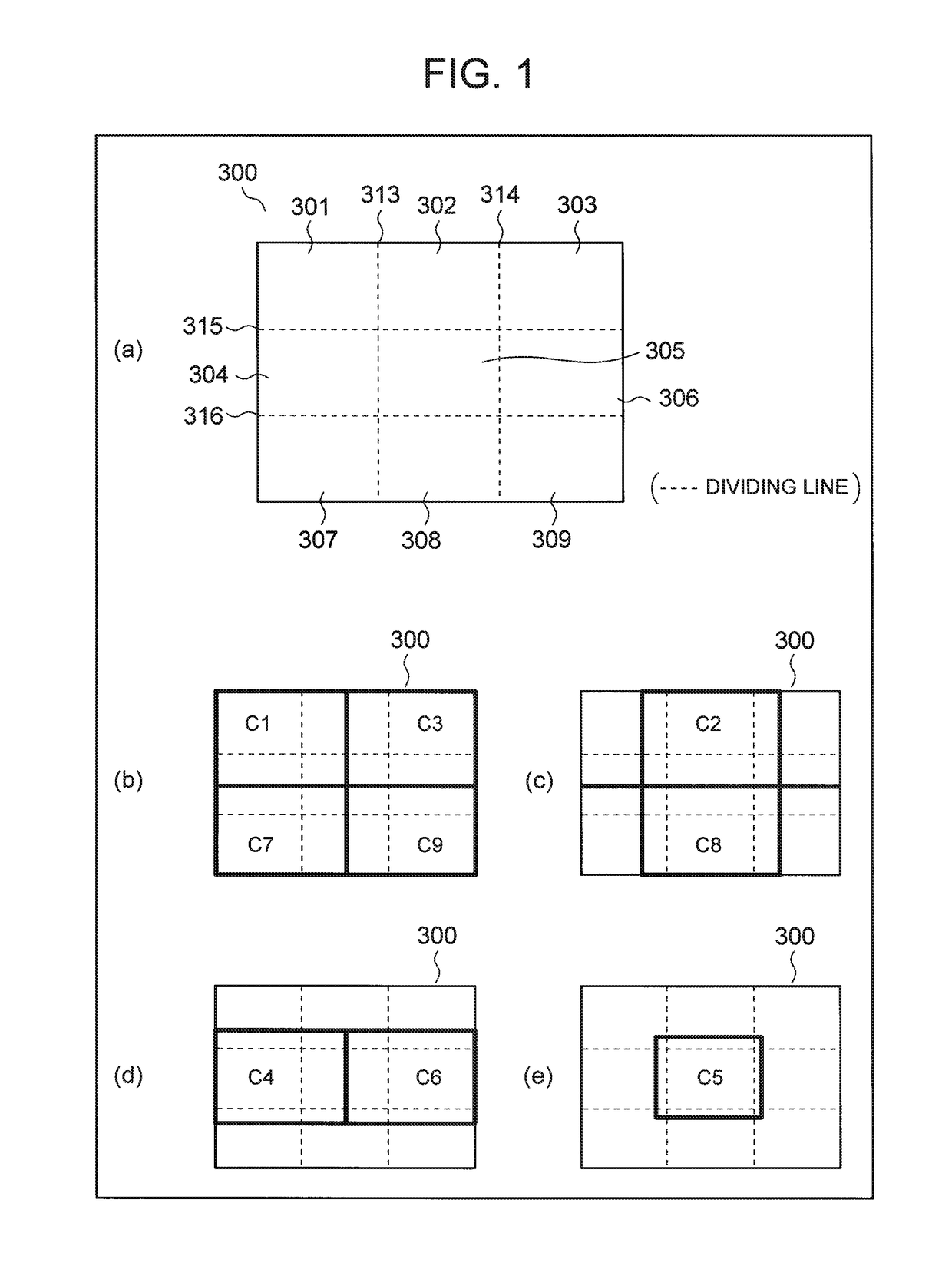
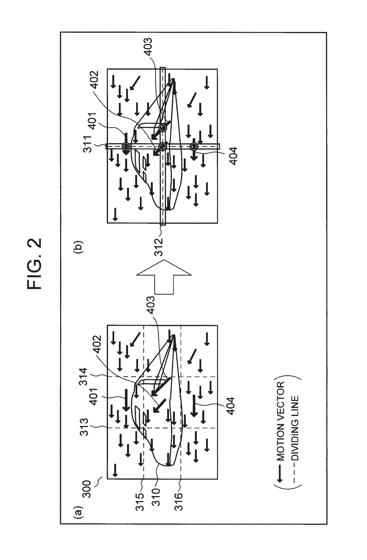
[0178]FIG. 1 is an explanatory diagram for describing an example of a process of a video encoding device in an exemplary embodiment of the present invention. (a) in FIG. 1 depicts an example of screen division. In the example depicted in (a) in FIG. 1, one screen 300 is divided into 3×3 (=9) equal-sized divided screens 301 to 309.

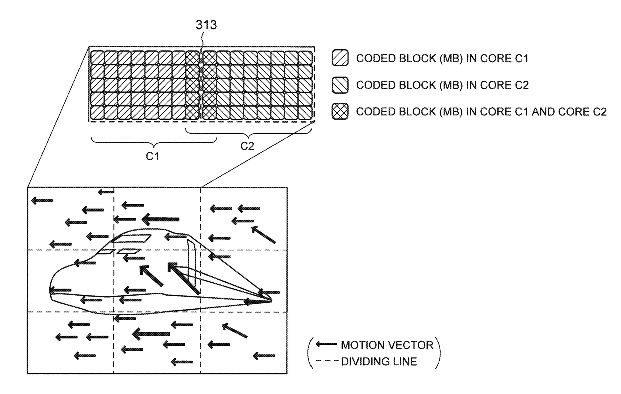
[0179](b) to (e) in FIG. 1 are explanatory diagrams for describing areas to be encoded by cores C1 to C9. The structure of the video encoding device in this exemplary embodiment is the same as the structure depicted in FIG. 36. The cores C1 to C9 correspond to the first video encoders depicted in FIG. 36. Though FIG. 36 depicts four first video encoders 102A, 102B, 102C, and 102D, FIG. 1 depicts an example of using nine cores C1 to C9.

[0180]As depicted in (b) to (e) in FIG. 1, the cores C1, C3, C7, and C9 respectively perform an encoding process for upp...


PUM


Abstract

A video encoding device includes: first video encoding means for encoding an input image to generate first coded data; a buffer for storing the input image; coded data transcoding means for transcoding the first coded data generated by the first video encoding means, to generate second coded data; and second video encoding means for generating a prediction signal based on the second coded data supplied from the coded data transcoding means. The first video encoding means includes: dividing means for dividing the input image into a plurality of image areas; and at least one encoding means corresponding to the image areas each of which is made up of a plurality of blocks, and for performing encoding in units of blocks. The encoding means also encodes a block that is included in an image area adjacent with a dividing line in between and is located near the dividing line.

Description

[0001]This application is a National Stage Entry of PCT / JP2015 / 000399 filed on Jan. 29, 2015, which claims priority from Japanese Patent Application 2014-023089 filed on Feb. 10, 2014, the contents of all of which are incorporated herein by reference, in their entirety.FIELD OF THE INVENTION[0002]The present invention relates to a video encoding device to which a technique of distributing the computational load of a video encoding process is applied.BACKGROUND OF THE INVENTION[0003]In the video coding scheme based on Non Patent Literature (NPL) 1, each frame of digitized video is split into coding tree units (CTUs), and each CTU is encoded in raster scan order. Each CTU is split into coding units (CUs) and encoded, in a quadtree structure. Each CU is split into prediction units (PUs) and predicted. The prediction error of each CU is split into transform units (TUs) and frequency-transformed, in a quadtree structure. Hereafter, a CU of the largest size is referred to as “largest CU” ...

Claims


Application Information

Patent Timeline
Patent Type & Authority Patents(United States)
IPC IPC(8): H04N19/167H04N19/436H04N19/40H04N19/176H04N19/513
CPCH04N19/167H04N19/176H04N19/513H04N19/436H04N19/40
Inventor ISHIDA, TAKAYUKISHIMOFURE, KENSUKETSUJI, NAOYANAGAYAMA, SUGURUCHONO, KEIICHI
Owner NEC CORP
Why Eureka
Try Eureka