
Method and device for displaying ship vicinity information

a technology for displaying information and ship vicinity, which is applied in the direction of navigation, instruments, surveying and navigation, etc., can solve the problems of difficult to avoid the influence of ship waves and marine accidents, and achieve the effect of accurately expressing information

Active Publication Date: 2018-11-13
FURUNO ELECTRIC CO LTD
View PDF17 Cites 1 Cited by
  • Summary
  • Abstract
  • Description
  • Claims
  • Application Information

AI Technical Summary

Benefits of technology

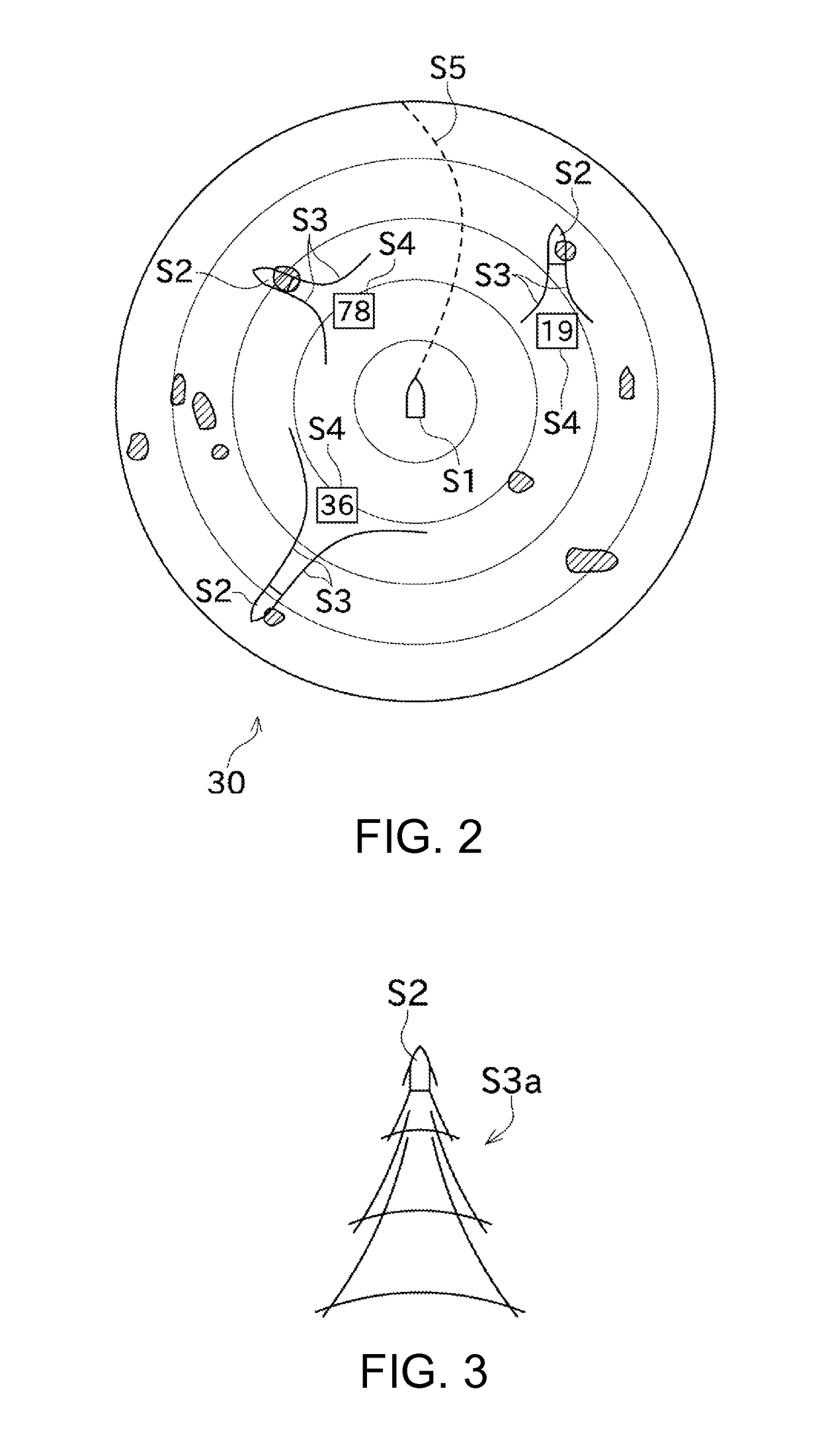
[0009]Thereby, since the information of the ship waves is graphically displayed on the display unit, a user can instinctively acknowledge the existence of the ship waves, and the influence of the ship waves becomes easier to be avoided. Moreover, by generating the information of ship waves caused by the second ship with the ship wave information generating module, the information of the ship waves caused in the vicinity of the first ship can be expressed accurately on the display unit.
[0029]Thereby, since the information of the ship waves is displayed graphically on the display device, the user can instinctively acknowledge the existence of the ship waves, and the influence of the ship waves becomes easier to be avoided. Moreover, by generating the information of the ship waves caused by the second ship, the information of the ship waves caused in the vicinity of the first ship can be expressed accurately on the display device.

Problems solved by technology

It has been pointed out that ship waves which are waves caused by ships traveling may cause marine accidents, such as capsizing of small ships or damage on moored ships.
However, in a case where ship waves which influence on a small ship occur therearound, it is difficult for the small ship to acquire information of the ship waves before the ship waves reach the small ship, and thus, it is difficult to avoid the influence of the ship waves.

Method used


Image

  • Method and device for displaying ship vicinity information
  • Method and device for displaying ship vicinity information
  • Method and device for displaying ship vicinity information

Examples


Embodiment Construction

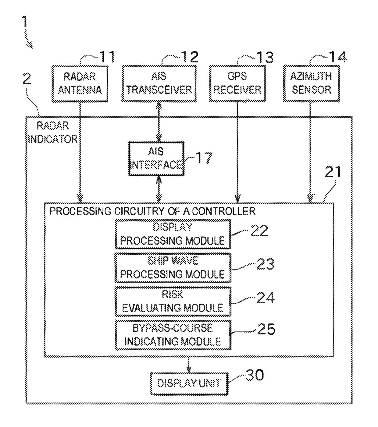
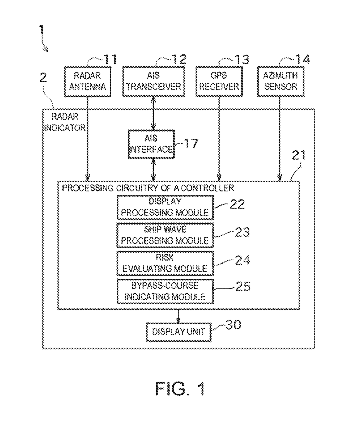
[0037]Next, one embodiment of this disclosure is described with reference to the appended drawings. FIG. 1 is a block diagram illustrating an overall configuration of a radar apparatus 1 including a radar indicator 2 according to one embodiment of this disclosure. FIG. 2 is a view illustrating one example of a display screen of a display unit 30 of the radar indicator 2.

[0038]As illustrated in FIG. 1, the radar apparatus 1 includes the radar indicator 2 of this embodiment (ship vicinity information display device). The radar apparatus 1 of this embodiment also includes a radar antenna 11, an AIS transceiver 12, a GPS receiver 13, and an azimuth sensor 14, and is installed in a ship (hereinafter, may be referred to as “the ship concerned,”“first ship”).

[0039]The radar antenna 11 transmits a pulse-shaped radio wave with strong directivity, and receives a reflection wave (radar echo) caused by the pulse-shaped radio wave reflecting on a target object and returned. Further, the radar an...


PUM


Abstract

A ship vicinity information display device is provided. The ship vicinity information display device includes a display unit configured to display information indicating a situation in the vicinity of a first ship, a detector configured to detect a second ship existing in the vicinity of the first ship, a ship wave information generating module configured to generate information of ship waves caused by the second ship, and a display processing module configured to cause the display unit to graphically display the second ship detected by the detector, and the information of the ship waves generated by the ship wave information generating module.

Description

CROSS-REFERENCE TO RELATED APPLICATION(S)[0001]This application claims priority under 35 U.S.C. § 119 to Japanese Patent Application No. 2014-183862, which was filed on Sep. 10, 2014, the entire disclosure of which is hereby incorporated by reference.TECHNICAL FIELD[0002]This disclosure generally relates to a ship vicinity information display device, which displays information indicating a situation in the vicinity of a ship on a display unit.BACKGROUND OF THE INVENTION[0003]It has been pointed out that ship waves which are waves caused by ships traveling may cause marine accidents, such as capsizing of small ships or damage on moored ships. Recently, due to the increase in maximum speed of ships, the number of ships traveling while generating large ship waves increased, which makes it easier to cause dangerous ship waves.[0004]Regarding such ship waves, various studies have been conducted, of which results include a method of estimatedly calculating ship waves disclosed in “Compari...

Claims


Application Information

Patent Timeline
Patent Type & Authority Patents(United States)
IPC IPC(8): G01C21/00G01S7/12G01S7/22G01S13/86G01S13/93G01S13/937
CPCG01S7/12G01S13/9307G01S13/86G01S7/22G01S13/937
Inventor ISE, TAKESHI
Owner FURUNO ELECTRIC CO LTD
Learn More