Distortion Compensation Circuit

a compensation circuit and distortion compensation technology, applied in the direction of digital transmission, phase-modulated carrier system, modulation, etc., can solve the problems of large change in the passing phase amount, the output signal amplitude cannot be reduced to a predetermined value, and the difficulty of improving power efficiency, so as to achieve low distortion characteristics of power amplifiers, increase circuit scale, and increase compensation data

Inactive Publication Date: 2007-10-04
PANASONIC CORP
View PDF5 Cites 21 Cited by
  • Summary
  • Abstract
  • Description
  • Claims
  • Application Information

AI Technical Summary

Benefits of technology

[0136] According to the invention, a distortion compensating circuit can be provided in which, in the polar modulation system, while suppressing increase of compensation data and increase of the circuit scale, a modulated signal can be correctly expressed, or low-distortion characteristics of a power amplifier can be realized.

Problems solved by technology

When the related quadrature modulation system is applied to a linear modulation system, therefore, it is difficult to improve the power efficiency.
Due to the leakage components, there arise problems in that the output signal amplitude cannot be reduced to a predetermined value or smaller, and that the passing phase amount is largely changed.

Method used


Image

  • Distortion Compensation Circuit
  • Distortion Compensation Circuit
  • Distortion Compensation Circuit

Examples


first embodiment

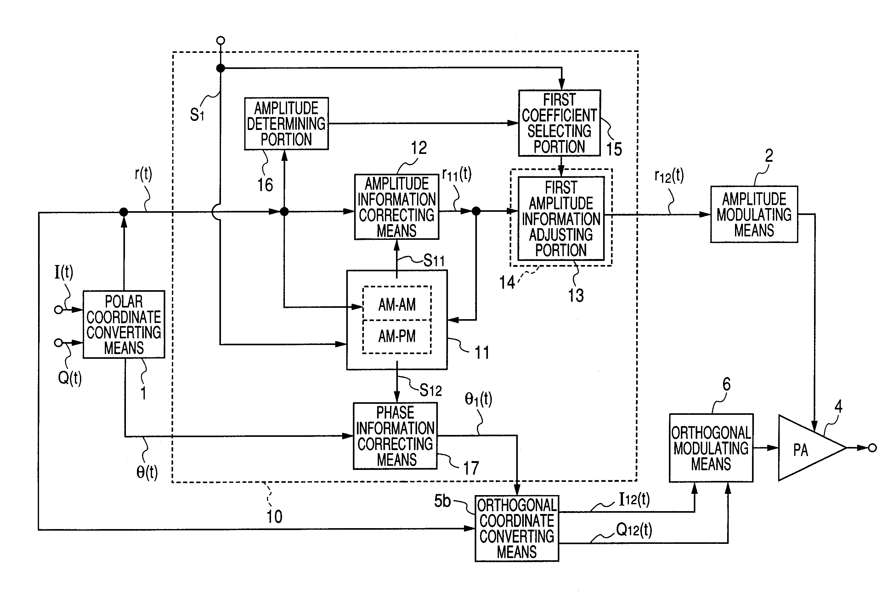
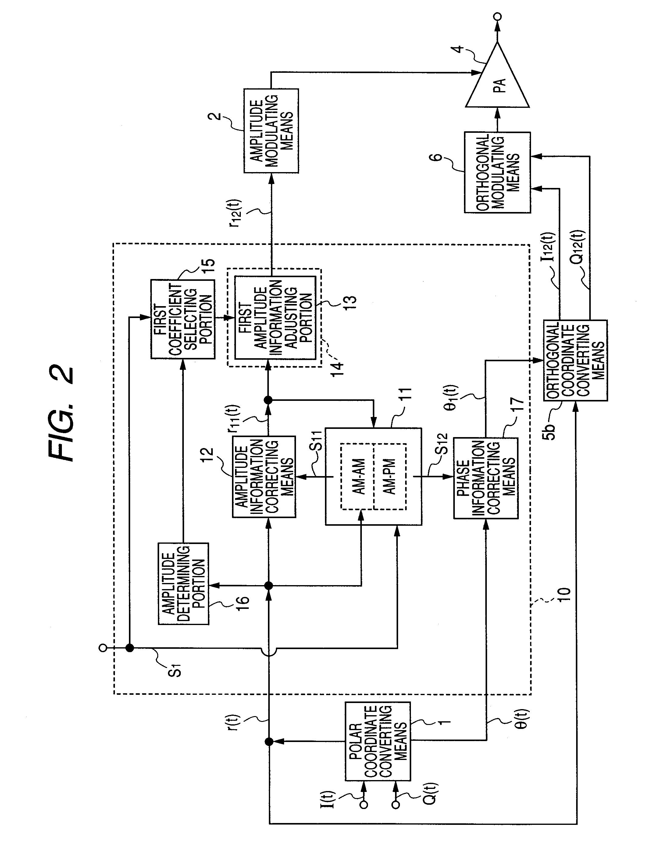
[0202] A first embodiment of the invention describes a method which has not been solved by any combination of related arts 1 to 3, and which, in the polar modulation system, realizes linearization of an output of a power amplifier with respect to a control voltage without producing increase of the circuit scale due to increase of distortion compensation data.

[0203] As another technique for realizing linearization of an output of a power amplifier with respect to a control voltage, there is a method which performs a process of comparing transmission data with demodulated data of an output signal from a power amplifier, and updating compensation data so as to reduce an error (hereinafter, referred to as adaptive process). A method will be described which realizes linearization of an output of a power amplifier with respect to a control voltage without using a feedback system in order to avoid lowering of the transmission efficiency of a transmitting apparatus caused by a branching po...

second embodiment

[0258] A second embodiment of the invention describes a method which has been described in the first embodiment of the invention, and in which, in the polar modulation system, while suppressing increase of compensation data, amplitude / phase information relating to a modulated signal is correctly expressed by performing phase compensation based on a signal to which transient characteristic compensation is reflected.

[0259]FIG. 6 is a view showing an example of a schematic configuration of a polar modulating circuit of the second embodiment of the invention, and FIG. 7 is a view showing another example of the schematic configuration of the polar modulating circuit of the second embodiment of the invention. The portions which are duplicated with those of the polar modulating circuit of FIG. 1 or 2 which has been described in the first embodiment of the invention are denoted by the same reference numerals.

[0260] As shown in FIGS. 6 and 7, in a distortion compensating circuit 20 of the ...

third embodiment

[0268] A third embodiment of the invention describes a method different from the first embodiment of the invention, relating to a method which, in the polar modulation system, realizes linearization of an output of a power amplifier with respect to a control voltage without using a feedback system, in order to avoid lowering of the transmission efficiency of a transmitting apparatus caused by a branching portion for an output signal of the power amplifier that is required in the configuration a circuit for performing a process of comparing transmission data with demodulated data of an output signal from the power amplifier, and updating compensation data so as to reduce an error (hereinafter, referred to as adaptive process).

[0269] Furthermore, the embodiment describes a method of easily adjusting the inclination of the AM-AM characteristics of the power amplifier in order to compensate frequency and temperature characteristics of the power amplifier, and the like.

[0270]FIG. 8(a) ...


PUM


Abstract

A distortion compensating circuit is provided in which, in the polar modulation system, while suppressing increase of compensation data and increase of the circuit scale, a modulated signal can be correctly expressed, or low-distortion characteristics of a power amplifier can be realized.
Based on a steady characteristic compensating circuit 11 which stores an output signal amplitude and output phase characteristics with respect to a control voltage in a steady state, amplitude adjustment is executed on amplitude information r11(t) on which amplitude correction is performed, by a first amplitude information adjusting portion 13, whereby the output-response characteristics of an output signal amplitude of an amplifier with respect to a change of the control voltage can be improved.

Description

TECHNICAL FIELD [0001] The present invention relates to a distortion compensating circuit which compensates distortion of an output signal of an amplifier that drives a control voltage to control the amplitude of the output signal with respect to a predetermined amplitude of an input high-frequency signal. BACKGROUND ART [0002] In a recent mobile phone service, a demand for data communication in addition to a voice call is increasing, and hence improvement of the transmission speed is important. In the GSM (Global System for Mobile communications) system which is in widespread use mainly in Europe and Asia, for example, a voice call is conventionally performed by the GMSK modulation in which the phase of a carrier is shifted in accordance with transmission data. However, the EDGE (Enhanced Data rates for GSM Evolution) system has been proposed in which also data communication is performed by 3π / 8 rotating 8-PSK modulation (hereinafter, abbreviated to 8-PSK modulation) in which bit i...

Claims


Application Information

Patent Timeline
Patent Type & Authority Applications(United States)
IPC IPC(8): H03F1/30H04L27/20
CPCH04L27/367H03F1/3282
Inventor SHIMIZU, YOSHITOSAITO, NORIAKI
Owner PANASONIC CORP
Why Eureka
Try Eureka