Spark plug extension

a spark plug and extension technology, applied in the direction of spark plugs, transformers, electrical equipment, etc., can solve the problems of expensive extension design and limited space available under the hood, and achieve the effect of preventing leakage of high voltage current and preventing damag

Active Publication Date: 2018-12-25
SEM AB
View PDF7 Cites 1 Cited by
  • Summary
  • Abstract
  • Description
  • Claims
  • Application Information

AI Technical Summary

Benefits of technology

[0006]It is an object of the present invention to solve, or at least to minimise the above mentioned problems, providing an easy and quick way of removing / introducing the ignition coil assembly from / into an engine cylinder head. This is achieved by an ignition coil assembly according to the appended claim 1, wherein the assembly comprises an elongated and flexible extension body which comprises an upper end portion and a lower end portion and where said extension body is arranged to be transversally bendable in relation to a main axis so that the upper end portion and the lower end portion of the extension body may assume an angle in relation to each other between 0 -360°.
[0009]Thanks to the invention there is achieved an assembly which is very easy to handle and which may be configured to fit a large variety of engine types, having various dimensions of the well. Thanks to the extension body the assembly can be adapted in length to a particular well, and due to the flexible property of the extension body, the ignition coil assembly can even be designed to fit deep wells (i.e. requiring a long extension body) without running into practical difficulties when removing / introducing the assembly due to limited space inside the motor compartment. In case of a very lengthy assembly, which normally would pose a problem in a narrow motor compartment, an assembly body according to the invention may simply be bent (e.g. during removal of the assembly) and can thus be adapted to the space available around the well under the hood of the vehicle. Furthermore, it facilitates providing compact engine compartments.
[0011]According to yet another aspect of the invention, the spark plug is detachably arranged within a detachable spark plug boot which is removably mounted at a lower end portion of the extension body. Preferably said spark plug boot is made of a flexible and heat resistant material such as silicone rubber, arranged to tightly embrace the spark plug to provide an isolating layer and prevent leakage of high voltage current. In a preferred embodiment the spark plug boot is arranged to be fitted within an adapter unit (a spark plug boot adapter) which in its turn is attached to a second joining section at the lower end portion of the extension body. The adapter unit is preferably made of a heat resistant and isolating material, such as ceramics or high temperature plastic, whereby there is achieved an efficient insulator between the spark plug and the second lowermost joining section of the assembly. Thanks to this aspect there is achieved the benefit that the soft and heat sensitive parts of the assembly, such as the extension body often being made of a resilient material such as rubber, are protected from the heat of the spark plug and are therefore also kept from destruction. An overheated rubber part could otherwise cause the assembly to break down which may result in difficulties during removal of the assembly or replacement of parts, and / or cause leakage of current. Preferably the spark plug boot is easy to detach from the spark plug adapter and at the same time is dimensioned with regards to its diameter to allow for a spark plug socket to reach the spark plug.

Problems solved by technology

As a diesel engine lacks spark plugs they are not designed to be serviced and the engine is therefore normally not adapted to promote easy access of any plug.
However, the space available under the hood is often rather limited, even quite narrow, and the lack of space may lead to difficulties when removing and / or introducing the ignition coil assembly from / into the motor.
This problem leads to a need of costly design of extensions, e.g. dividing it in several parts.

Method used


Image

  • Spark plug extension
  • Spark plug extension
  • Spark plug extension

Examples


Embodiment Construction

[0019]The invention will hereinafter be described in more detail with reference to the appended drawings. The following description should be considered as preferred form only, and is not decisive in a limiting sense.

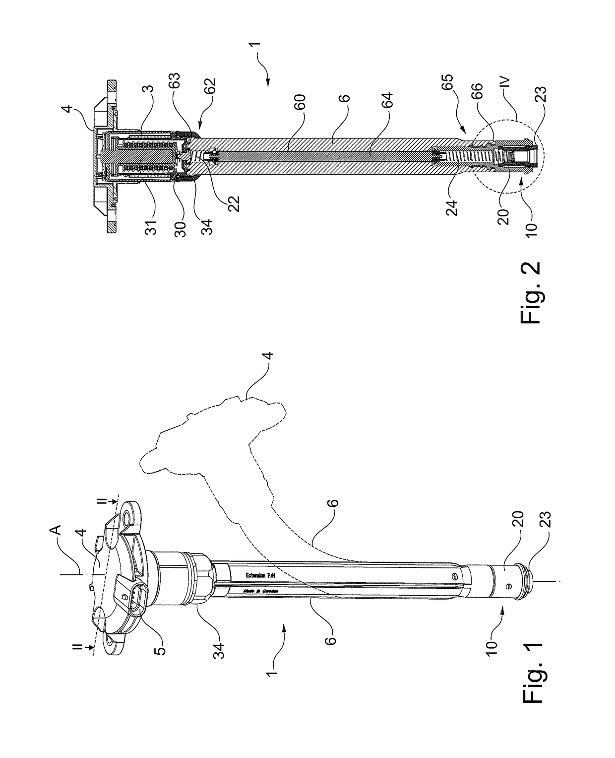
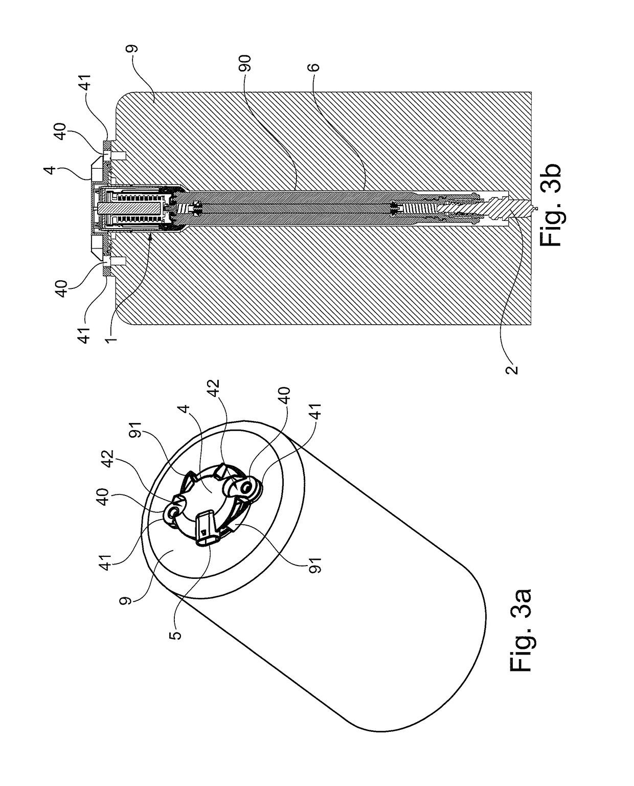
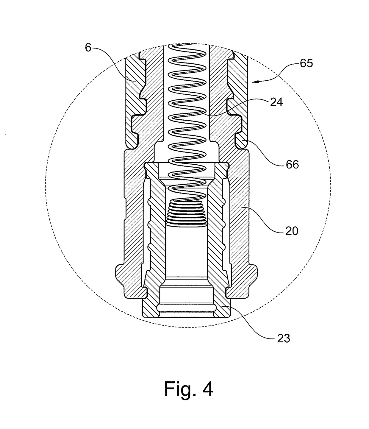
[0020]In FIGS. 1-6 the ignition coil assembly is generally designated 1. In FIG. 1 is shown a perspective view of an embodiment of an assembly 1 according to the invention, and FIG. 2 shows a cross section of the assembly according to line II in FIG. 1. The main parts of the assembly 1 comprise a spark plug receiving end portion 10, an ignition coil 3 and an elongated extension body 6. The assembly 1 is configured for insertion in a well 90 of a cylinder head 9 (see FIGS. 3a-b) which is associated with an internal combustion engine. The spark plug receiving end portion 10 and the coil 3 are connected to each other by means of the elongated extension body 6 which comprises an inner, generally cylindrical, through bore 60 through which there is arranged an interconnecting...


PUM

PropertyMeasurementUnit
lengthaaaaaaaaaa
distanceaaaaaaaaaa
distanceaaaaaaaaaa

Abstract

The following invention relates to an ignition coil assembly for an ignition system comprising an ignition coil where said assembly has a main axis and is configured for insertion into and / or removal out of a well associated with an internal combustion engine, wherein the assembly comprises an elongated extension body made of flexible material, said extension body comprising an upper end portion and a lower end portion wherein the extension body is arranged to be transversally bendable in relation to the main axis so that the upper end portion and the lower end portion may assume an angle (α) in relation to each other.

Description

CROSS REFERENCE TO RELATED APPLICATIONS[0001]This application is a 35 U.S.C. § 371 national stage of International Application No, PCT / SE2013 / 050535 filed on May 14, 2013, published in English under PCT Article 21(2), which claims the benefit of priority to Swedish Patent Application No. 1250485-8 file on May 14, 2012, the disclosures of which are hereby incorporated by reference.TECHNICAL FIELD[0002]The present invention relates to an ignition coil assembly for a spark ignited internal combustion engine comprising an ignition coil where said assembly has a main axis and is configured for insertion in a spark plug well.BACKGROUND ART[0003]Internal combustion engines comprise spark plugs for initiating combustion driving the engine piston and require a spark to ignite the compressed fuel. Conventionally an ignition coil transforms the battery's low voltage to high voltage needed to create an electric spark in the spark plugs to ignite the fuel. Common for all plugs is that they are a...

Claims


Application Information

Patent Timeline
Patent Type & Authority Patents(United States)
IPC IPC(8): H01F38/12H01T13/04F02P3/02H01T13/44
CPCH01T13/04F02P3/02H01T13/44H01F38/12Y10T29/49231
Inventor ANDERSSON, LARS-AKEBENGTSSON, JORGENGUSTAFSSON, BERT
Owner SEM AB
Why Eureka
Try Eureka