Trimmer head

a technology of trimmer head and spool, which is applied in the field of trimmer head, can solve the problems of reducing the moment of inertia of the head, increasing the rotational speed, and lengthening the protruding wire portions, and achieves the effects of simplifying and speeding up the replacement operation of the cutting wire spool, especially lightweight and compa

Active Publication Date: 2019-01-01
TECOMEC
View PDF62 Cites 1 Cited by
  • Summary
  • Abstract
  • Description
  • Claims
  • Application Information

AI Technical Summary

Benefits of technology

[0007]It is an object of the present invention to provide a trimmer head that overcomes the drawbacks of the heads available at present.
[0008]One advantage of the trimmer head is that replacement operations of the cutting wire spool are simplified and speeded up.
[0009]Another advantage of the trimmer head is that it is particularly lightweight and compact.

Problems solved by technology

The shortening of such portions reduces the moment of inertia of the head, which consequently increases its rotational speed.
The activation of the unwinding device causes a lengthening of the protruding wire portions and an increase of the moment of inertia of the head.

Method used


Image

  • Trimmer head
  • Trimmer head
  • Trimmer head

Examples


Embodiment Construction

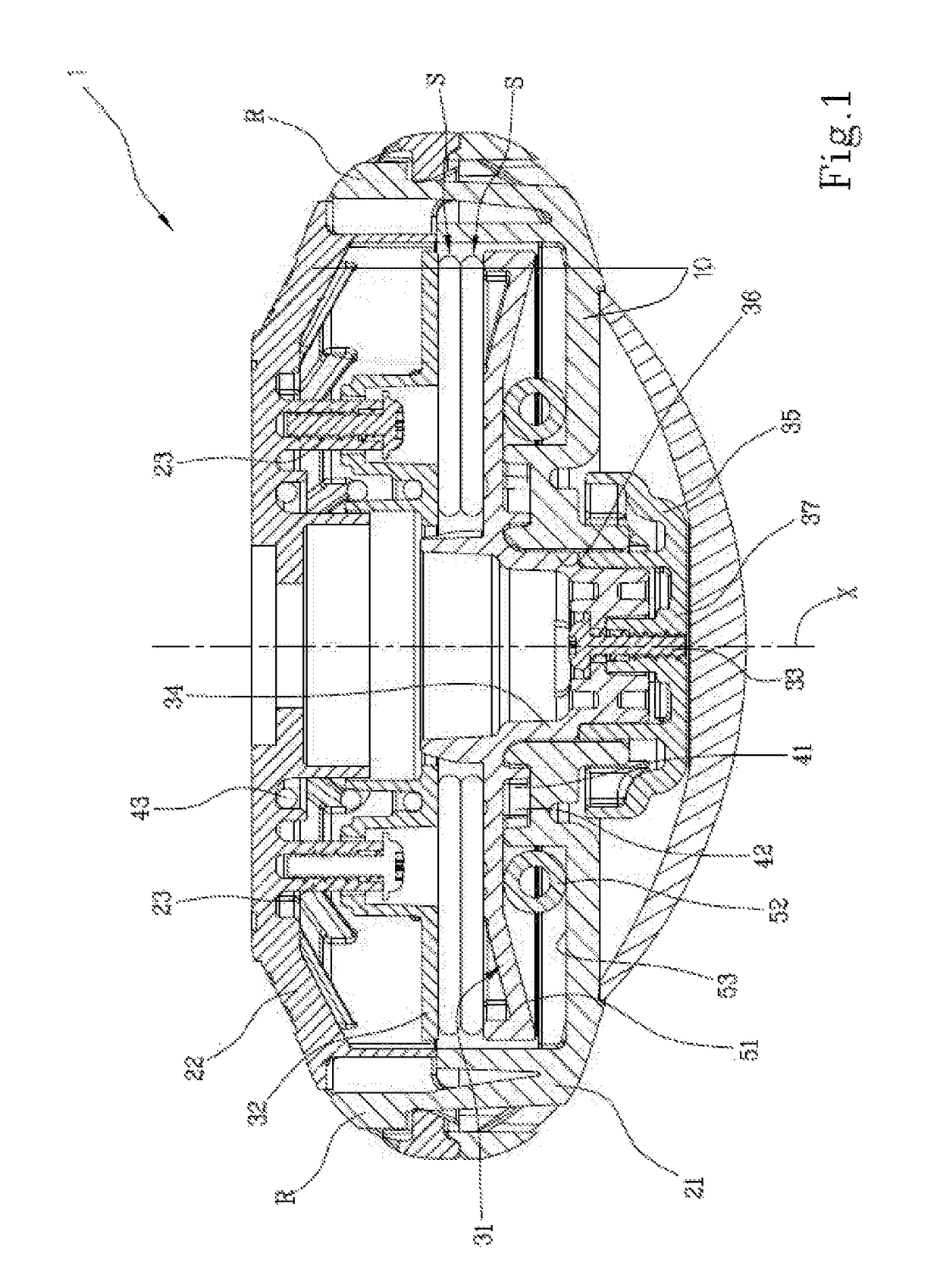
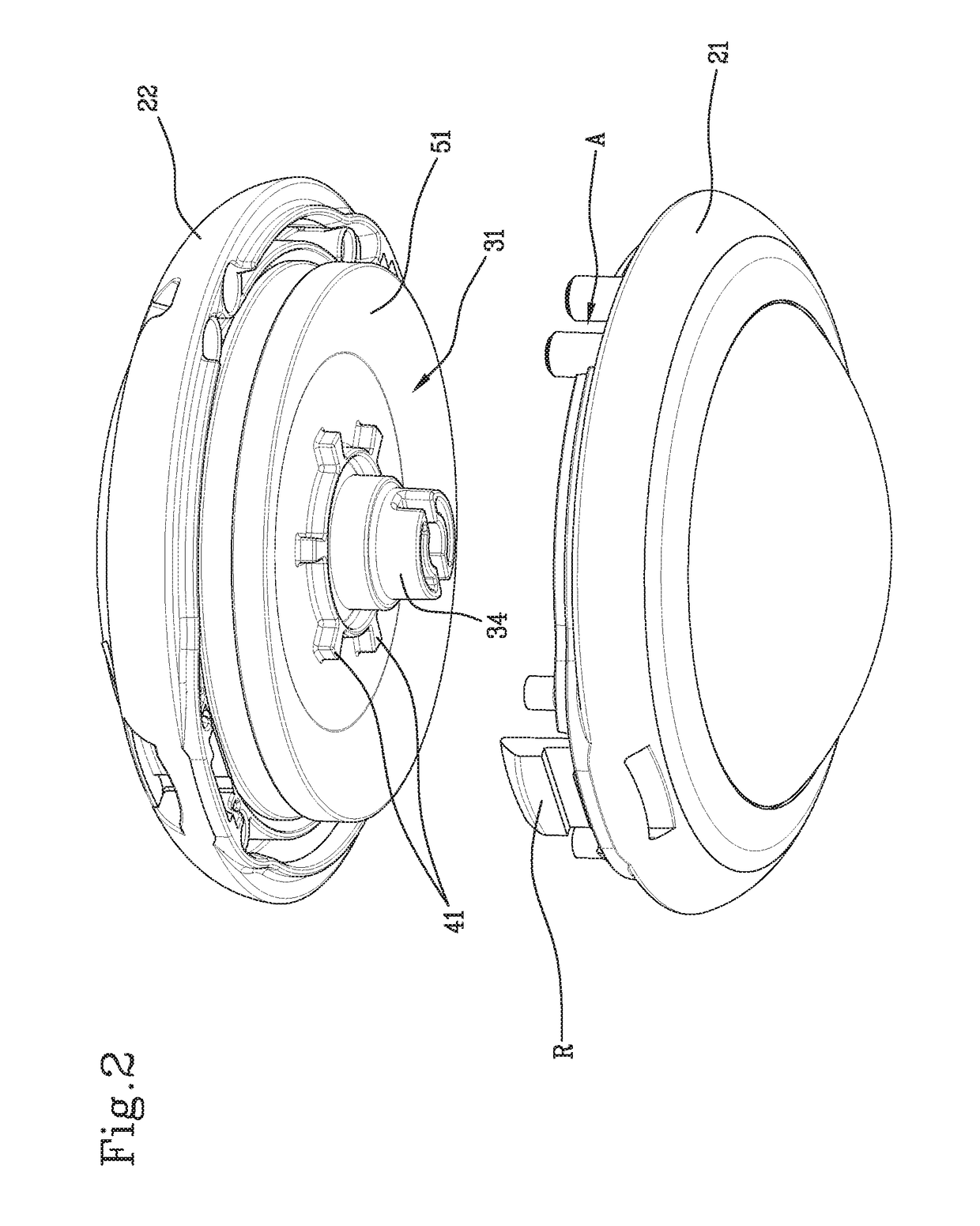
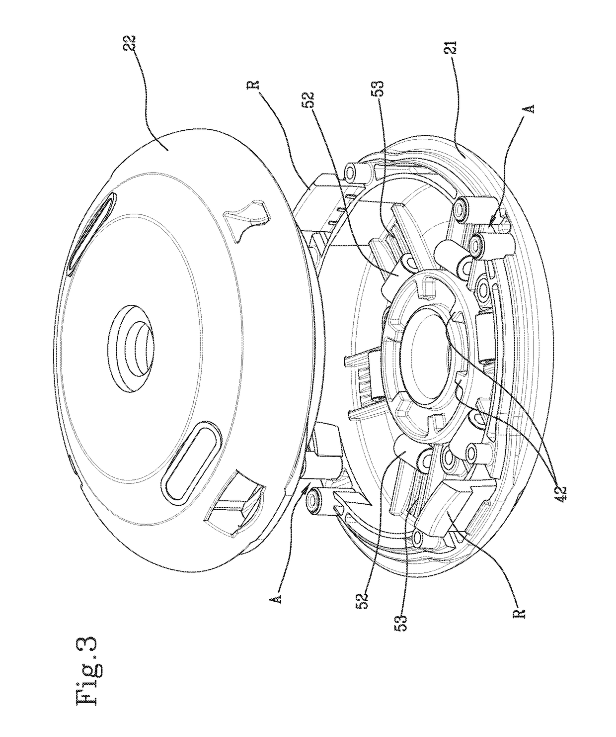
[0015]The trimmer head (1) according to the present invention comprises a casing (10), designed to be coupled to a driveshaft for rotating about a main axis (X), the casing (10) comprising an upper shell (22) and a lower shell (21), the lower shell (21) comprising a second toothing (42) that protrudes upwardly and a track (53) that is oriented radially with respect to the main axis (X). The casing (10) is provided with one or more openings (A) in order to afford passage of respective end portions of the cutting wire (W). A cutting wire spool (S) is housed inside the casing (10) between a lower disk (31) and an upper disk (32). The lower disk (31) includes a first toothing (41) that protrudes downwardly. In an engagement position, the upper disk (32) and the lower disk (31) rotate with the lower shell (21). In a free position, the upper disk (32) and the lower disk (31) rotate with respect to the lower shell (21). This relative rotation is aimed at causing unwinding of a given portio...


PUM


Abstract

A trimmer head that includes a casing to be coupled to a driveshaft. The casing includes an upper shell and a lower shell, with the lower shell including a second toothing that protrudes upwardly. The trimmer head further includes an upper disk and a lower disk within the casing, with the lower disk including a first toothing that protrudes downwardly. A spool of cutting wire is positioned between the lower disk and the upper disk. In an engagement position, the first toothing and the second toothing are engaged and the upper disk and lower disk rotate with the lower shell. In a free position, the first toothing and the second toothing are disengaged and the upper disk and lower disk rotate with respect to the lower shell.

Description

FIELD OF THE INVENTION[0001]The present invention is related to a trimmer head.[0002]The invention particularly relates to a head provided with an automatic cutting wire unwinding device.BACKGROUND OF THE INVENTION[0003]Several examples of heads of this type are currently available on the market. These heads comprise a casing internally of which a winding-reel is housed for winding a wire cutting spool. Two portions of the cutting wire protrude outwardly through dedicated openings in the casing. The winding-reel is associated to the casing and can take on an engagement position, wherein it is rotatingly solid with the casing, and a free position, wherein it can rotate with respect to the casing. Notoriously, the free position of the winding-reel is exploited to cause unwinding of the wire spool with the purpose of restoring the length of the cutting wire portions which protrude outward of the casing. The automatic cutting wire unwinding device allows the winding-reel to move between...

Claims


Application Information

Patent Timeline
Patent Type & Authority Patents(United States)
IPC IPC(8): A01D34/416
CPCA01D34/416A01D34/4166A01D34/4162
Inventor CIGARINI, ENRICOLONGO, SALVATORE
Owner TECOMEC
Why Eureka
Try Eureka