
Printing apparatus and control method

a printing apparatus and control method technology, applied in printing and other directions, can solve the problems of inability to eject ink, inability to print ink, and inability to absorb ink by the ink absorbing body, etc., and achieve the effect of increasing the size and complexity of the apparatus

Active Publication Date: 2019-01-08
SEIKO EPSON CORP
View PDF11 Cites 0 Cited by
  • Summary
  • Abstract
  • Description
  • Claims
  • Application Information

AI Technical Summary

Benefits of technology

[0007]An advantage of some aspects of the invention is to provide an ink jet type printing apparatus having a mechanism which wipes a nozzle surface, which can appropriately prevent the apparatus from ink scattering when ink adhering to a wiper blade is scraped off without an increase in size and complexity of the apparatus.
[0009]According to the aspect, since the blade member is sequentially separated from the scraping member in one direction, an ink scattering direction can regulate (control) when the wiper blade passes through the cleaner. Therefore, by appropriately designing the shapes of the tip surface of the blade member and the tip surface of the scraping member, a region where the ink is not desired to be scattered, such as a printing region can be reliably prevented from ink scattering. Therefore, the region where ink is not desired to be scattered can be reliably prevented from ink scattering without an increase in size and complexity of the printing apparatus.
[0011]According to the aspect, since the blade member is sequentially separated from the scraping member in one direction, an ink scattering direction can regulate (control) when the wiper blade passes through the cleaner. Therefore, by appropriately designing the shapes of the tip surface of the blade member and the tip surface of the scraping member, a region where the ink is not desired to be scattered, such as a printing region can be reliably prevented for ink scattering. Therefore, the region where ink is not desired to be scattered can be reliably prevented for ink scattering without an increase in size and complexity of the printing apparatus.
[0014]According to the aspect, by appropriately designing the inclination angle of the scraping member, an ink scattering amount in a forward path and a backward path of the wiper blade can be controlled. Specifically, ink scattering to the printing region can be prevented. Also, in the aspect, the region where ink is not desired to be scattered can be reliably prevented from ink scattering without an increase in size and complexity of the printing apparatus.
[0016]According to the embodiment, the ink scattering amount can increase when the wiper blade passes through the cleaner in the first direction.
[0018]According to the aspect, by appropriately designing the shape of the scraping member, the ink scattering amount in the forward path and the backward path of the wiper blade can be controlled. Specifically, ink scattering to the printing region can be prevented. Also, in the aspect, the region where ink is not desired to be scattered can be reliably prevented from ink scattering without an increase in size and complexity of the printing apparatus.

Problems solved by technology

In such a state, there are problems that the ink ejection direction becoming unstable, ink ejection being impossible, and the like are generated.
However, a method described in JP-A-2007-152940 described above has a risk that ink absorbed by the ink absorbing body thickens and causes malfunction.
In addition, as another method, there is a method that can move a rubber plate of a wiper while abutting on a cleaner (scraping member) and scrape off the adhering ink, but in that case, there is a problem that ink is scattered when the wiper passes through the cleaner.
In order to protect other portions from ink scattering, a cover is provided in all directions in a movement direction of the wiper, and in a backward path of the wiper, means is taken to provide a mechanism that does not abut on the cleaner, but in either case, it is not preferable because an increase in size and complexity of the apparatus are generated.

Method used


Image

  • Printing apparatus and control method
  • Printing apparatus and control method
  • Printing apparatus and control method

Examples


Embodiment Construction

[0050]Hereinafter, embodiments of the invention will be described with reference to the drawings. However, such an embodiment does not limit the technical scope of the invention. In the drawings, the same or similar elements are described by being denoted the same reference numerals or reference symbols.

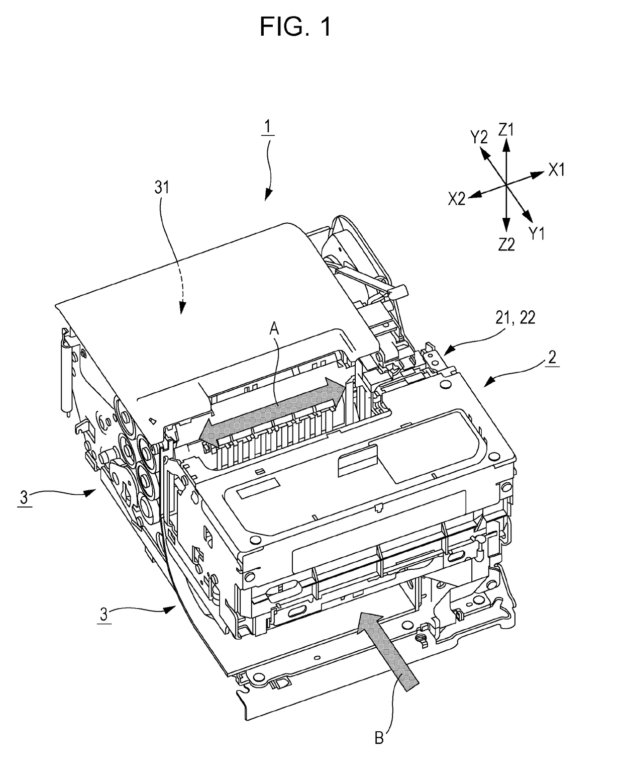
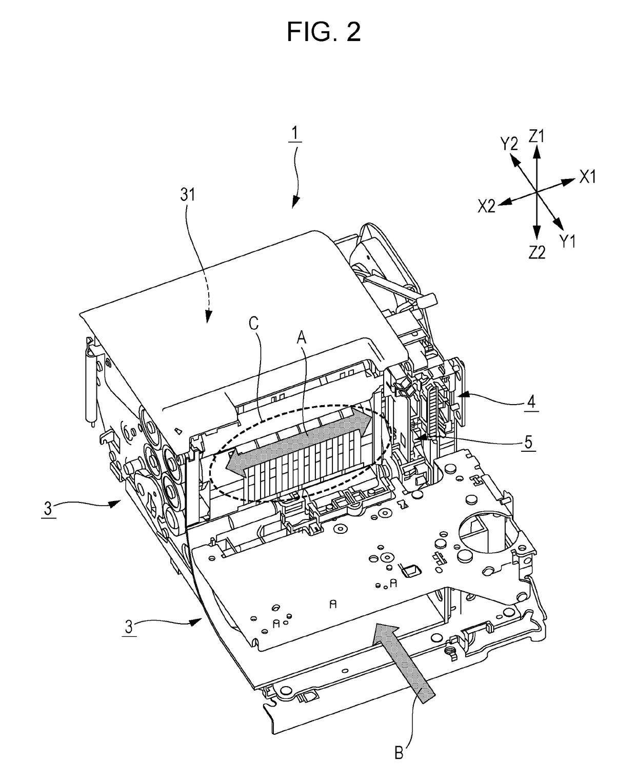
[0051]FIG. 1 and FIG. 2 are perspective views according to an embodiment of a printing apparatus to which the invention is applied. FIG. 1 illustrates an entire mechanism portion of an inside portion of a casing of the printing apparatus and FIG. 2 illustrates a portion in which a printing mechanism 2 and the like is excluded from the drawing illustrated in FIG. 1.

[0052]A printer 1 illustrated in FIG. 1 and FIG. 2 is the printing apparatus to which the invention is applied and the printer 1 includes a wiper unit 5 for cleaning a nozzle surface. The printer 1 is characterized by a shape of a wiper blade 51 and a cleaner 52 constituting the wiper unit, and according to shape thereof, a...


PUM


Abstract

There is provided a printing apparatus which performs printing by ejecting ink from a nozzle, including: a wiper blade that abuts on a nozzle surface on which an opening of the nozzle is formed, and moves in a first direction to wipe the ink adhering to the nozzle surface; and a cleaner that abuts on the moving wiper blade and scrapes off the ink adhering to the wiper blade, in which the wiper blade includes a blade member which protrudes in a second direction which is substantially orthogonal to the first direction, and in which the cleaner includes a scraping member which protrudes in a third direction which is a direction opposite to the second direction.

Description

BACKGROUND1. Technical Field[0001]The present invention relates to an ink jet type printing apparatus including a mechanism for wiping a nozzle surface, and more particularly to a printing apparatus that can appropriately prevent an apparatus from ink scattering when ink adhering to a wiper blade is scraped off without an increase in size and complexity of the apparatus.2. Related Art[0002]In the related art, an ink jet type printer is used widely. In such a printer, a print head includes a plurality of nozzles that discharge (eject) ink onto a print medium, but ink may adhere to the vicinity of a nozzle opening portion and be solidified. In such a state, there are problems that the ink ejection direction becoming unstable, ink ejection being impossible, and the like are generated.[0003]Therefore, in the related art, a wiper made of a rubber plate or the like is provided to clean an ink ejecting surface (nozzle surface). In addition, after cleaning, cleaning for scraping off the ink...

Claims


Application Information

Patent Timeline
Patent Type & Authority Patents(United States)
IPC IPC(8): B41J2/165
CPCB41J2/16538B41J2/16544B41J2/16541B41J2002/16573
Inventor URABE, YUICHIARAFUKA, KAZUSHIINOUE, KEN
Owner SEIKO EPSON CORP
Learn More