
Sound wave sensor, correction value setting device, and distance detecting device

a technology of correction value and sensor, applied in the direction of measurement device, using reradiation, instruments, etc., can solve the problems of sensor size and complexity increase, and achieve the effect of simplifying the structure of the sound wave sensor

Active Publication Date: 2017-06-20
DENSO CORP
View PDF32 Cites 1 Cited by
  • Summary
  • Abstract
  • Description
  • Claims
  • Application Information

AI Technical Summary

Benefits of technology

[0005]However, since the above sound wave sensor needs to incorporate a structure for transmitting and receiving sound waves of different frequencies, the sensor may increase in size and complexity.
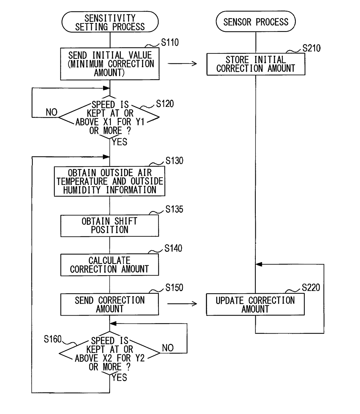
[0008]Since the correction value for the sensitivity is obtained from outside, the sound wave sensor can be simplified in structure compared to when the sound wave sensor corrects the sensitivity by itself by transmitting and receiving sound waves of multiple frequencies.

Problems solved by technology

However, since the above sound wave sensor needs to incorporate a structure for transmitting and receiving sound waves of different frequencies, the sensor may increase in size and complexity.

Method used


Image

  • Sound wave sensor, correction value setting device, and distance detecting device
  • Sound wave sensor, correction value setting device, and distance detecting device
  • Sound wave sensor, correction value setting device, and distance detecting device

Examples


Embodiment Construction

[0024]Below, an embodiment of the present disclosure is described with reference to the drawings.

Structure of Present Embodiment

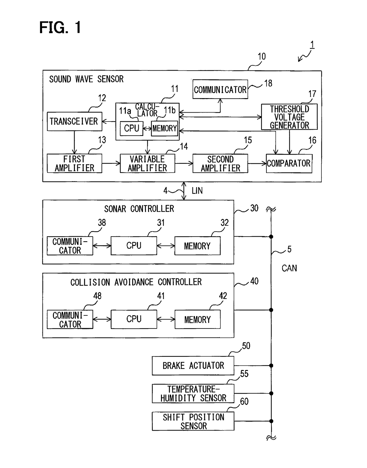
[0025]A distance detecting system 1 according to an embodiment of the present disclosure is mounted to, for example, a vehicle (subject vehicle) such as a car, detects obstacles such a wall and another vehicle beside or behind the subject vehicle, and performs control such as braking if it will cause problems in a movement of the subject vehicle. As shown in FIG. 1, the distance detecting system 1 includes a sound wave sensor 10, a sonar controller 30, a collision avoidance controller 40, a brake actuator 50, a temperature-humidity sensor 55, and a shift position sensor 60.

[0026]The sound wave sensor 10 and the sonar controller 30 are connected to each other by a communication line 4 where communication is performed by using LIN protocol, for example. The sonar controller 30, the collision avoidance controller 40, the brake actuator 50, the temperature-humi...


PUM


Abstract

A sound wave sensor in a distance detecting system determines a presence or absence of a target object and a distance to the target object by receiving, with a preset sensitivity, a reflected wave obtained from a transmitted sound wave reflected by the target object. A correction value used to correct the sensitivity of the sound wave sensor is obtained from outside the sound wave sensor, and the sensitivity is corrected by using this correction value.

Description

CROSS REFERENCE TO RELATED APPLICATIONS[0001]This application is a U.S. National Phase Application under 35 U.S.C. 371 of International Application No. PCT / JP2013 / 006305 filed on Oct. 24, 2013 and published in Japanese as WO 2014 / 068924 A1 on May 8, 2014. This application T is based on and claims the benefit of priority from Japanese Patent Applications No. 2012-238008 filed on Oct. 29, 2012. The entire disclosures of all of the above applications are incorporated herein by reference.TECHNICAL FIELD[0002]The present disclosure relates to a sound wave sensor for detecting a distance to a target object by transmitting and receiving a sound wave, a correction value setting device for setting a correction value for the sound wave sensor, and a distance detecting device.BACKGROUND ART[0003]A sound wave sensor was proposed that has a function to correct its own sensor characteristics by transmitting sound waves of different frequencies and by detecting effects of humidity and temperature ...

Claims


Application Information

Patent Timeline
Patent Type & Authority Patents(United States)
IPC IPC(8): G01S7/52G01S15/87G01S7/529G01S15/93G01S15/08G01S15/04G01S15/931
CPCG01S7/52004G01S7/52006G01S7/529G01S15/04G01S15/08G01S15/876G01S15/931
Inventor NAKANO, AKIOMATSUURA, MITSUYASUAKIYAMA, KEIKO
Owner DENSO CORP
Learn More