Bearing isolator seal with tapered static shutoff O-ring interface

a static shutoff o-ring and isolator technology, which is applied in the direction of engine seals, shafts and bearings, bearing components, etc., can solve the problems of affecting the service life of rotating equipment, so as to improve the static seal and minimize wear and resistance , the effect of cost-effectiveness

Active Publication Date: 2019-01-15
FLOWSERVE PTE LTD
View PDF26 Cites 0 Cited by
  • Summary
  • Abstract
  • Description
  • Claims
  • Application Information

AI Technical Summary

Benefits of technology

[0010]A cost effective bearing isolator seal that includes a static shut off feature based on a shut off O-ring is tolerant of axial misalignment between the rotor and stator, provides an improved static seal between the rotor and the stator, and minimizes wear and resistance when the rotor is rotating relative to the stator.
[0011]The stator of the bearing isolator seal includes a tapered section located in an inboard region of the interface between the rotor and stator, adjacent to the shut off O-ring. When the rotor is static, and there is no axial misalignment between the rotor and the stator, the shut off O-ring's nominal inside diameter is pressed against the tapered section of the stator, forming an enhanced static seal. The angle of the taper is toward the rotor, which biases the shut off O-ring against the shut off O-ring's containment groove on the rotor, enabling the static seal when no misalignment is present.
[0012]When the rotor is rotating and is axially separated from the stator due to axial misalignment, the interference of the shut off O-ring's nominal inside diameter with the tapered section is reduced. And in embodiments, when the target maximum misalignment is reached, the interference between the shut off O-ring's inner diameter and the stator becomes a “line on line” fit, thereby maintaining static shut off capability throughout the axial misalignment range.
[0013]In embodiments, the bearing isolator seal also includes labyrinth technology that further enhances the exclusion of contaminants. In some of these embodiments, a close radial clearance is maintained between the rotor and stator at the location of the tapered section and below the centerline of the O-ring cross section, thereby maximizing the effectiveness of the rotor groove in creating contact with the O-ring and ensuring lift off with rotation. Although the axial overlap of the rotor with the stator is reduced as the rotor shifts axially away from the stator during operation, the radial clearance remains unchanged.
[0015]It will therefore be apparent to one of ordinary skill in the art that the present invention does not avoid or simply tolerate axial misalignment, but instead takes advantage of axial misalignment. Due to the tapered section of the stator in the present invention, the interference between the O-ring and the stator is increased when the rotor is idle and in its neutral position, and decreased when the rotor is in operation and axially misaligned with the stator. Accordingly, when the rotor is rotating, the interference between the shut off O-ring and the stator is reduced by both a radial shifting and an axial shifting of the O-ring, due to outward expansion of the O-ring inner diameter by centripetal acceleration, and due to the axial shifting of the O-ring away from the tapered section of the stator. The result is an enhanced static seal when the bearing isolator seal is idle and reduced wear and resistance when the bearing isolator seal is in operation.

Problems solved by technology

The main purpose of a bearing isolator seal is to prevent the ingress of process fluid or other contaminants into the bearing, which can lead to premature failure of the lubrication and bearings.
In fact, penetration by contaminants is the most common reason for rotating equipment failure.
For many applications, lip seals and simple labyrinths have proven inadequate for preventing ingress of contamination into bearings.
Unfortunately, in this approach it can be difficult to provide a desired degree of static shut off without also avoiding any residual contact or “interference” between the O-ring and the stator when the rotor is rotating.
The result can be a compromise between wear and resistance due to residual O-ring interference when the mechanism is in operation, versus the degree of seal protection provided when the mechanism is idle.
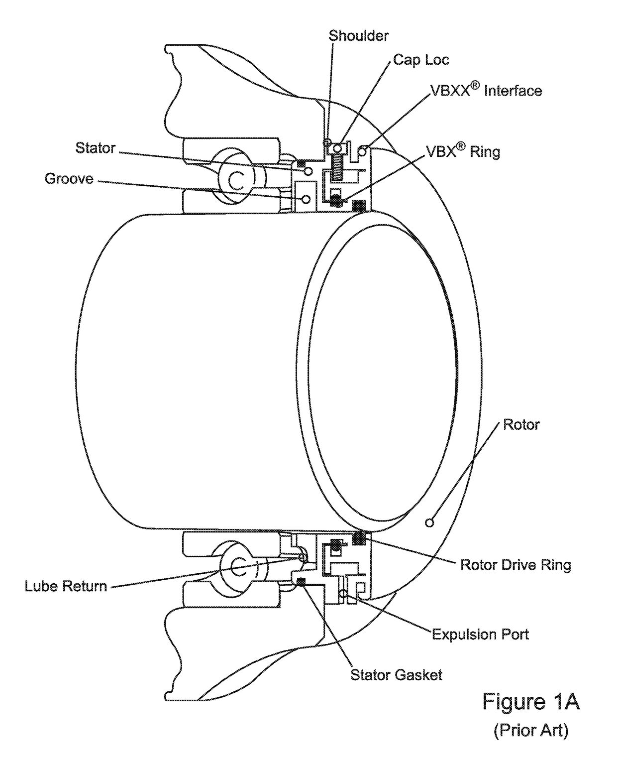
Typically, there can be a tendency for the rotor to move axially away from the stator during operation, causing axial “misalignment” between the rotor and the stator, and to return to a closer static or “neutral” position when the system is idle.
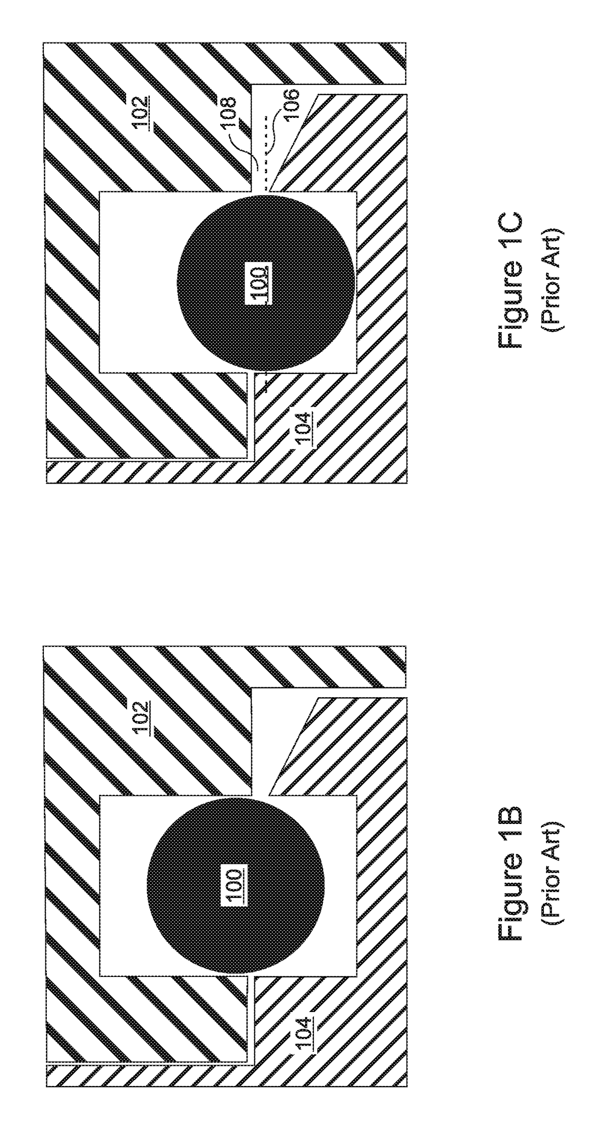
However, most shut off designs, such as the one shown in FIGS. 1B and 1C, are intolerant of axial misalignment between the rotor and the stator, and many require that the axial misalignment be limited to only 0.007 inch (0.18 mm) Total Indicator Reading (“TIR”) or less.
As a result, many applications that require a greater degree of tolerance to axial misalignment are not suitable for use with a simple shut off mechanism such as the one shown in FIGS. 1B and 1C, and require use of other, more complicated and expensive designs.

Method used


Image

  • Bearing isolator seal with tapered static shutoff O-ring interface
  • Bearing isolator seal with tapered static shutoff O-ring interface
  • Bearing isolator seal with tapered static shutoff O-ring interface

Examples


Embodiment Construction

[0032]The present invention is a cost effective bearing isolator seal, including a static shut off feature based on a shut off O-ring, that is tolerant of axial misalignment between the rotor and stator, provides an improved static seal between the rotor and the stator, and minimizes wear and resistance when the rotor is rotating relative to the stator.

[0033]With reference to FIG. 3A, the stator 300 of the bearing isolator seal includes a tapered section 302 located in an inboard region of the interface between the rotor 304 and stator 300, adjacent to the shut off O-ring 306. Because FIG. 3A is a cross-sectional illustration, the tapered section appears as in inclined section. When the rotor 304 is static, and there is no axial misalignment between the rotor 304 and the stator 300, the shut off O-ring's nominal inside diameter is pressed against the tapered section 302 of the stator, forming an enhanced static seal. The angle of the tapered section 302 is toward the rotor 304, whic...


PUM


Abstract

A bearing isolator seal having a shut off O-ring is tolerant of axial rotor-stator misalignment and provides an enhanced static seal while minimizing rotational wear. A tapered section of the stator is overlapped by the shut off O-ring. When the rotor is static there is no axial misalignment, and the shut off O-ring is pressed against the tapered section, forming an enhanced seal. During rotor rotation, increased axial misalignment moves the O-ring away from the tapered section, reducing rotational wear. The stator can extend horizontally beyond the tapered section and below the O-ring, so that if the rotor moves beyond a maximum misalignment, there is a “line on line” fit between the stator and rotor. The bearing isolator seal can include labyrinth technology, and the tapered section can include a contour that allows the shutoff O-ring to drag along the surface of the tapered section with no hang-ups or binding.

Description

RELATED APPLICATIONS[0001]This application is a national phase application filed under 35 USC § 371 of PCT Application No. PCT / US2015 / 064422 with an International filing date of Dec. 8, 2015 which claims the benefit of U.S. Provisional Application No. 62 / 088,808, filed Dec. 8, 2014. Each of these applications is herein incorporated by reference in its entirety for all purposes.FIELD OF THE INVENTION[0002]The invention relates to bearing isolator seals, and more particularly, to bearing isolator seals that include a static shutoff O-ring.BACKGROUND OF THE INVENTION[0003]Bearing isolator seals are commonly used in a variety of rotating shaft applications when it is necessary to exclude contaminants or process fluid from reaching internal mechanisms such as shaft support bearings, or from leaking out of a housing that is penetrated by the rotating shaft.[0004]For example, bearing isolator seals are used in bearing housings for pumps, motors, gearboxes and other pieces of rotating equip...

Claims


Application Information

Patent Timeline
Patent Type & Authority Patents(United States)
IPC IPC(8): F16J15/32F16J15/447F16J15/16F16C33/72
CPCF16J15/447F16C33/72F16J15/4478F16J15/32F16J15/164
Inventor BENDER, ROBERT PAULMALOCHA, JASON MATTHEWBARKER, JOSEPH CHARLES
Owner FLOWSERVE PTE LTD
Why Eureka
Try Eureka