Filter device

Active Publication Date: 2019-01-29
HYDAC FILTERTECHNIK GMBH
View PDF12 Cites 0 Cited by
  • Summary
  • Abstract
  • Description
  • Claims
  • Application Information

AI Technical Summary

Benefits of technology

[0003]In view of these issues, a problem addressed by the invention is to provide a filter device of the type

Problems solved by technology

Given the large quantities in which such filter devices are used, the produc

Method used


Image

  • Filter device
  • Filter device

Examples


Embodiment Construction

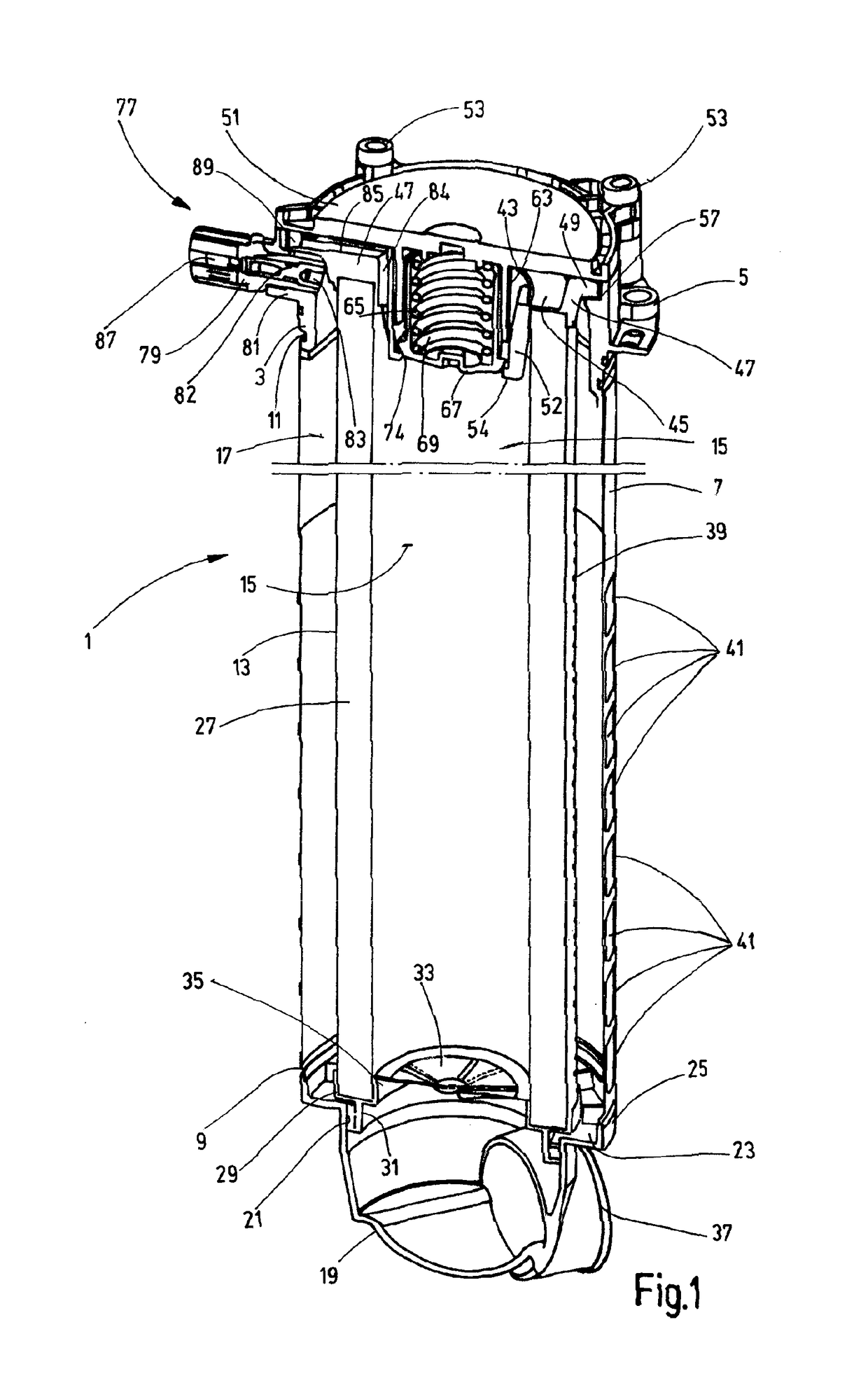
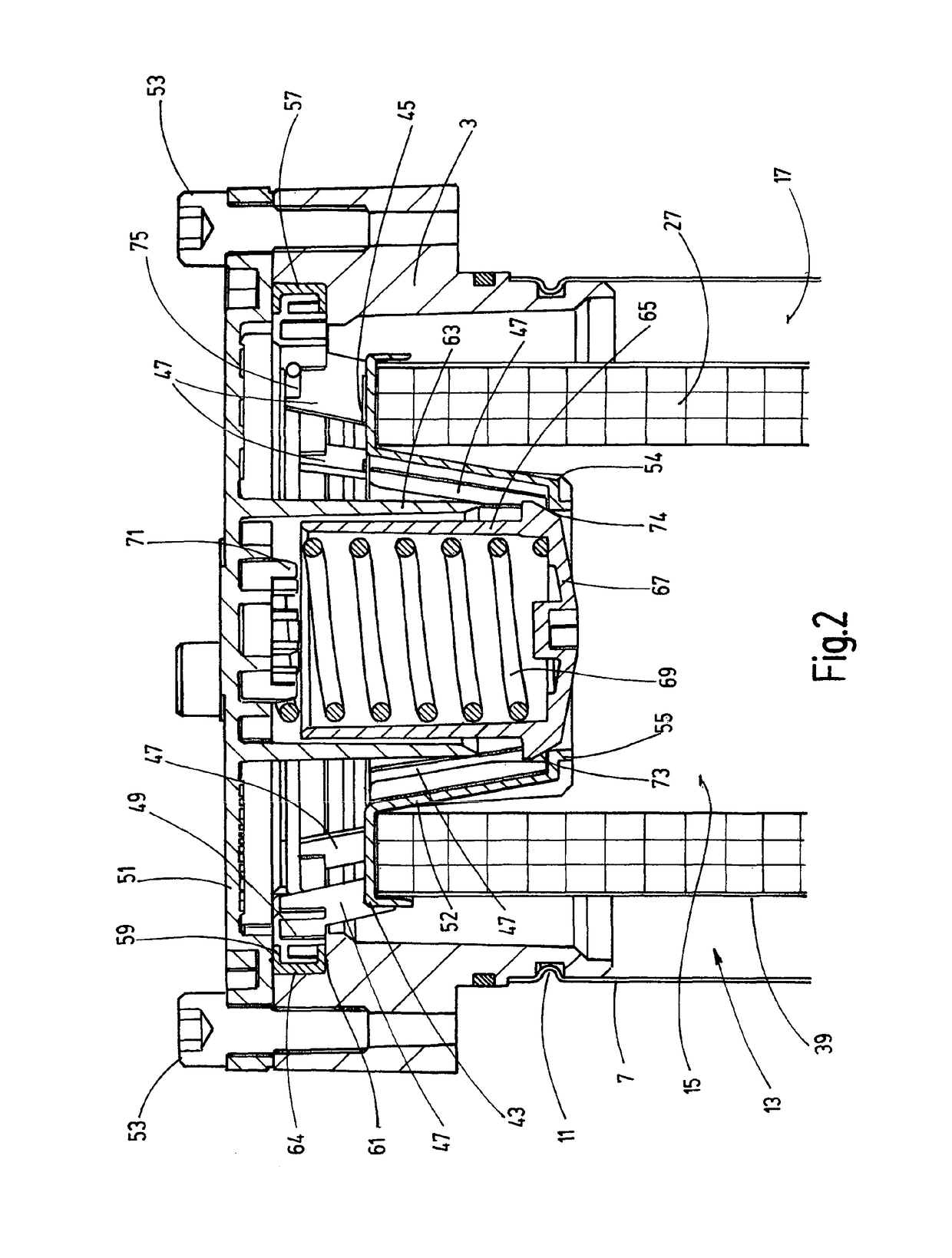
[0019]With reference to the attached drawings, the invention is explained using the example of an in-tank filter device, in which the filter housing 1 has a filter head 3, on which flange parts 5 are located at the outside. The filter housing 1 can be mounted by these flange parts on the edge of a top wall opening of a storage container or tank (not depicted) in such a way that a filter bowl 7, which is connected to the bottom end of the filter head 3, extends in the vertical direction into the inside of the tank. The length of the filter bowl 7 depicted truncated in FIGS. 1 and 2 is such that the bottom end 9 of the filter bowl 7 is located below the lowest level of fluid, e.g. hydraulic oil, to be expected during operation. In the design as an in-tank filter device, in the depicted example the filter bowl 7 is in the form of a relatively thin-walled circular cylinder and is fixed on the filter head 3 by a flanging 11. The invention can be advantageously used not only in in-tank fi...


PUM

PropertyMeasurementUnit
Pressureaaaaaaaaaa
Distanceaaaaaaaaaa
Circumferenceaaaaaaaaaa

Abstract

A filter device has a filter housing (1) with a filter head (3), a filter pot (7) and a removable housing cover part (51) and has a filter element (13) separating a non-filtrate side (15) from a filtrate side (17) in the housing. A bypass valve device has a valve closure element (65) preloaded by a closing spring (69) into a closed position in which it bears against a valve seat part (74). If the filter element (13) is blocked, the closure element opens up a fluid path from the non-filtrate side (15) to the filtrate side (17), by passing the filter element (13). The valve closure element (65) and the closing spring (69) are on the cover part (51). The valve seat part (74) is on an element cap (43) of the filter element (13). The element cap has a receiving part (45) forming an enclosure for that end of the filter material (27) of the filter element (13) facing toward the cover part (51).

Description

FIELD OF THE INVENTION[0001]The invention relates to a filter device having a filter housing with a filter head, a filter bowl and a removable housing cover part. A filter element accommodated in the filter housing separates a non-filtrate side from a filtrate side. A bypass valve device has a valve closure element preloaded by a closing spring into a closed position in which it bears against a valve seat part. In the case of a blocked filter element, the closure element passes into a position in which it opens up a fluid path from the non-filtrate side to the filtrate side, bypassing the filter element.BACKGROUND OF THE INVENTION[0002]Filter devices of this kind are state of the art and can be easily commercially obtained in a variety of designs. To cite just one example from the large number of known devices of this kind, reference is made to document EP 2 249 941B1, for example. When filter devices of this kind are used in technical equipment, such as hydraulic systems, the opera...

Claims


Application Information

Patent Timeline
IPC IPC(8): B01D29/23B01D37/04B01D35/143B01D35/147B01D29/60B01D35/153
CPCB01D29/23B01D29/606B01D35/147B01D35/153B01D37/046B01D35/1435B01D2201/295
Inventor SAKRASCHINSKY, MICHAELKLEIN, VOLKMAR
Owner HYDAC FILTERTECHNIK GMBH
Why Eureka
Try Eureka