Air valve connecting device

a technology of connecting device and air valve, which is applied in the direction of functional valve types, machines/engines, and positive displacement liquid engines, etc., can solve the problems of increasing manufacturing cost and manufacturing procedures, and achieves the effects of convenient connection, convenient operation or operation, and simplified or improved structur

Inactive Publication Date: 2019-02-19
BETO ENG & MARKETING
View PDF13 Cites 0 Cited by
  • Summary
  • Abstract
  • Description
  • Claims
  • Application Information

AI Technical Summary

Benefits of technology

[0006]The primary objective of the present invention is to provide an air valve connecting device including a simplified or improved structure for easily connecting to various inflation valves and for being easily actuated or operated with a single hand of the user and for being easily manufactured with a decreased manufacturing procedure and cost.
[0007]In accordance with one aspect of the invention, there is provided an air valve connecting device comprising a housing including a chamber formed therein, and including a first end portion, a shank slidably engaged in the chamber of the housing and limited to slide relative to the housing, and prevented from pivoting and rotating relative to the housing, the shank including a bore formed therein for receiving a pressurized air, and the shank including a first end portion for receiving the pressurized air, and the shank including a second end portion, a barrel rotatably engaged with the shank and rotatably connected to the housing, and the barrel including an inner thread formed therein for engaging with an inflation valve and for detachably securing the inflation valve to the barrel, and a control ferrule rotatably engaged with the shank and rotatably connected to the housing, the control ferrule being slid and moved in concert with the housing and the barrel relative to the shank, and the control ferrule being threaded and engaged with the shank for forcing and moving the control ferrule and the housing and the barrel relative to the shank and for forcing and moving the second end portion of the shank toward and to engage with the inflation valve when the control ferrule is rotated relative to the shank and for allowing the inflation valve to be easily and quickly supplied and filled with the pressurized air.
[0008]The shank includes an outer thread formed thereon, and the control ferrule includes an inner thread formed therein for engaging with the outer thread of the shank and for forcing and moving the control ferrule and the housing and the barrel and the inflation valve relative to the shank longitudinally when the control ferrule is rotated relative to the shank and thus for allowing the second end portion of the shank to be easily and quickly and effectively forced and moved toward and to engage with the inflation valve with the control ferrule.
[0009]The first end portion of the shank is connected to a hose for receiving the pressurized air from the hose or from a pressurized air reservoir. A shield may further be provided and engaged onto the hose and the first end portion of the shank for clamping and securing the hose to the shank and for preventing the hose from being disengaged from the shank.
[0011]The barrel includes a gasket engaged into the barrel for softly and resiliently engaging with the inflation valve and for making an air or water tight seal between the barrel and the inflation valve. An anchor may further be provided and attached to the housing and engaged with the barrel for guiding and limiting the barrel to rotate relative to the housing and for preventing the barrel from moving longitudinally relative to the housing.
[0012]The barrel includes a peripheral recess formed therein, and the anchor includes a projection extended therefrom and engaged into the chamber of the housing and engaged with the peripheral recess of the barrel for guiding and limiting the barrel to rotate relative to the housing and for preventing the barrel from moving longitudinally relative to the housing. The control ferrule includes a peripheral depression formed therein, and the anchor includes a projection extended therefrom and engaged into the chamber of the housing and engaged with the peripheral depression of the control ferrule for guiding and limiting the control ferrule to rotate relative to the housing and for preventing the control ferrule from moving longitudinally relative to the housing.

Problems solved by technology

However, normally, the typical air valve connecting heads required to be provided with an actuating handle or hand grip to be grasped or held or operated with one hand of the user, and the user has to use the other hand to grasp and actuate or operate the valve housing, such that the typical air valve connecting heads comprise a structure that may not be easily operated or may not effectively grasping or holding the different inflation valves and may comprise a greatly increased manufacturing cost and manufacturing procedures.

Method used


Image

  • Air valve connecting device
  • Air valve connecting device
  • Air valve connecting device

Examples


Embodiment Construction

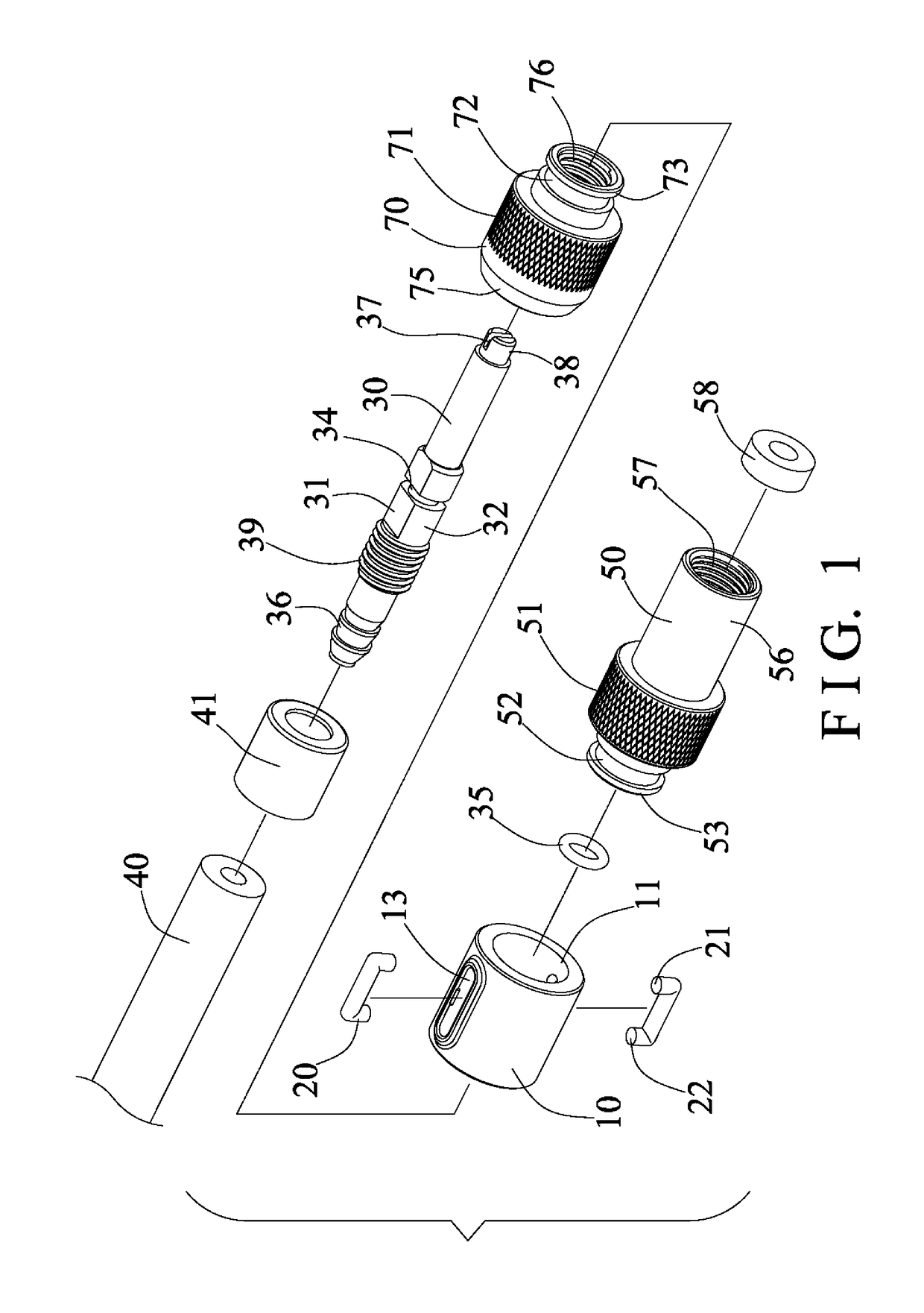
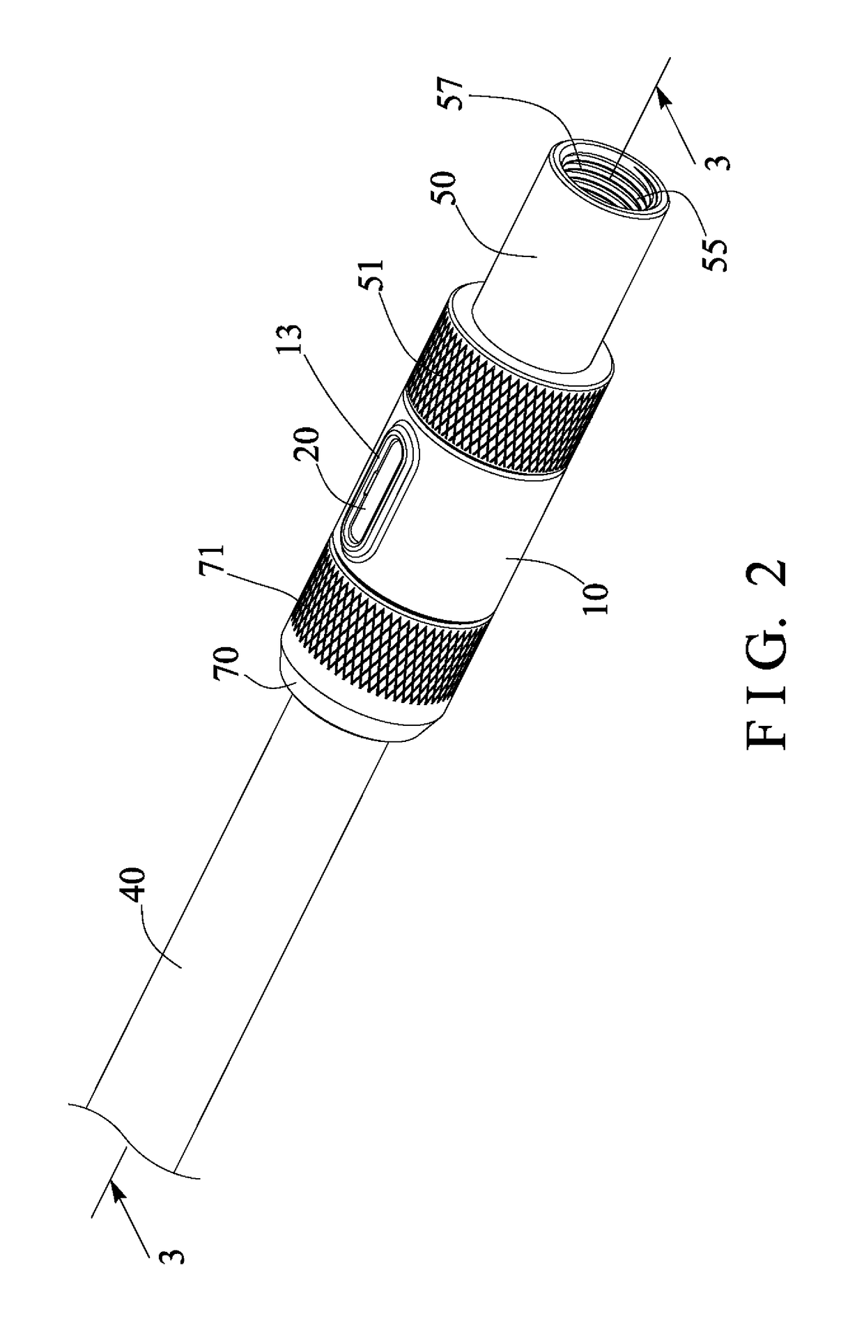
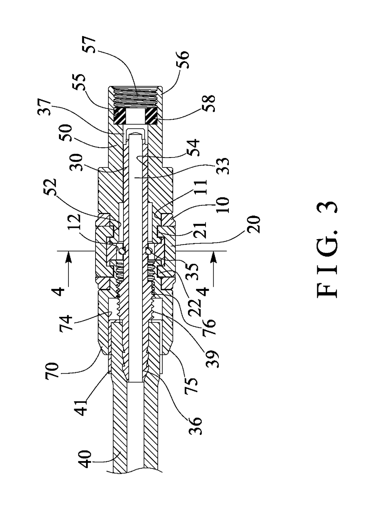
[0019]Referring to the drawings, and initially to FIGS. 1-4, an air valve connecting device in accordance with the present invention comprises a valve connecting body or housing 10 including a bore or chamber 11 formed therein, and including a non-circular portion or space or segment 12 formed or provided therein (FIGS. 3, 4), and including one or more (such as two) channels 13 oppositely formed therein and / or equally spaced from each other and partially intersecting or communicating with the chamber 11 of the housing 10 and each for receiving or engaging with a latch or anchor 20 therein. For example, the anchors 20 are attached to or engaged into the channels 13 of the housing 10 respectively and each anchor 20 include one or more (such as two) legs or projections 21, 22 extended therefrom and engaged into the chamber 11 of the housing 10, best shown in FIG. 3.

[0020]A mandrel or shank 30 is slidably received or engaged in the chamber 11 of the housing 10, and includes a non-circul...


PUM


Abstract

An air valve connecting device includes a housing, a shank slidably engaged in the housing and limited to slide relative to the housing, and prevented from pivoting and rotating relative to the housing, the shank includes one end portion for receiving the pressurized air, a barrel is rotatably engaged with the shank and connected to the housing for detachably securing the inflation valve to the barrel, and a control ferrule is connected to the housing and moved in concert with the housing and the barrel relative to the shank, and the control ferrule is threaded with the shank for forcing and moving the shank toward and to engage with the inflation valve when the control ferrule is rotated relative to the shank.

Description

BACKGROUND OF THE INVENTION1. Field of the Invention[0001]The present invention relates to an air valve connecting head or device, and more particularly to an air valve connecting device including a simplified or improved structure for easily connecting to various inflation valves and for being easily actuated or operated with a single hand of the user and for being easily manufactured with a decreased manufacturing procedure and cost.2. Description of the Prior Art[0002]Various kinds of typical air valve connecting devices have been developed and comprise a valve housing including one end for connecting or coupling to a pressurized air reservoir and for receiving the pressurized air from the pressurized air reservoir, and a fitting port formed in the other end of the valve housing for receiving or engaging with an inflation valve and for inflating the balls, the inner tires of the bicycles or the motorcycles or the vehicles, the present inventor has developed various kinds of air v...

Claims


Application Information

Patent Timeline
Patent Type & Authority Patents(United States)
IPC IPC(8): F16K15/20B60C29/00
CPCF16K15/20B60C29/005B60C29/00F04B33/005F04B39/10F04B39/123F04B39/14
Inventor WANG, LO PIN
Owner BETO ENG & MARKETING
Why Eureka
Try Eureka