Control valve for compressor

a compressor and control valve technology, applied in the direction of machines/engines, pumps, positive displacement liquid engines, etc., can solve the problems of increasing manufacturing costs, greatly reducing or reducing the working life of the typical variable displacement mechanism, etc., and achieve the effect of effectively actuating or operating, improving and simplifying the structure or configuration

Active Publication Date: 2019-04-25
CHU HENRY C
View PDF1 Cites 0 Cited by
  • Summary
  • Abstract
  • Description
  • Claims
  • Application Information

AI Technical Summary

Benefits of technology

[0011]The primary objective of the present invention is to provide a control valve for compressor including an improved and simplified structure or configuration for allowing the compressor of the refrigeration system to be effectively actuated or operated by the internally and externally controlled control valve.

Problems solved by technology

However, the typical variable displacement mechanisms for wobble plate type or slant plate type compressors should normally be actuated or operated at a rate ranging between 6-100%, and may not be shut off completely while in use, without an outside of compressor control device, such as a clutch device or a solenoid device.
However, the typical variable displacement mechanisms for wobble plate type or slant plate type compressors may only be controlled externally with the signals from the vehicle electrical control unit (ECU) or vehicle electrical control module (ECM), and should normally be actuated or operated at a fast speed such that the working life of the typical variable displacement mechanisms will be greatly reduced or decreased.
However, the typical variable displacement mechanisms include a complicated structure or configuration that may not be easily and quickly made or manufactured and that may include a complicated making or manufacturing procedure and that may include a greatly increased manufacturing cost or the like.

Method used


Image

  • Control valve for compressor
  • Control valve for compressor
  • Control valve for compressor

Examples


Embodiment Construction

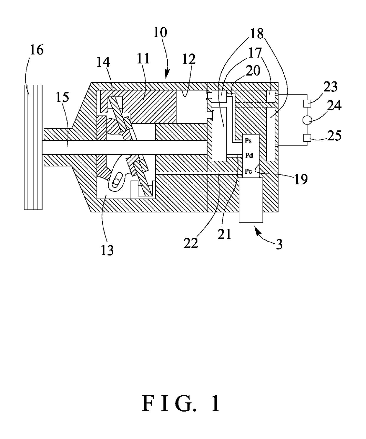
[0024]Referring to the drawings, and initially to FIG. 1, a compressor in accordance with the present invention comprises an outer receptacle or cylinder housing 10, and a number of pistons 11 slidably received or engaged in piston casings 12 that are formed and provided in the cylinder housing 10, and actuated or operated to move in a reciprocating action in the cylinder housing 10 for generating a pressurized air, the cylinder housing 10 includes a crank case chamber or control chamber 13 formed therein and communicating with the piston casings 12, and a swash plate 14 is rotatably received or engaged in the control chamber 13 of the cylinder housing 10 with a spindle 15 and connected or coupled to and engaged with the pistons 11 for changing and determining the moving stroke of the pistons 11, in which the spindle 15 is substantially parallel to the pistons 11. A driven pulley 16 is connected or coupled to the spindle 15 and rotated in concert with the spindle 15.

[0025]When the s...


PUM


Abstract

A compressor includes a cylinder housing having a number of pistons, a control chamber communicating with piston casings, a suction chamber and a discharge chamber communicating with the piston casings, a control valve includes a receptacle engaged in the cylinder housing, a valve member engaged in the receptacle for controlling the pressurized air to flow from the discharge chamber into the control chamber of the cylinder housing, and a valve element for controlling a bypass of the pressurized air through the receptacle. A bellow device is connected to actuate the sliding member internally, and a sliding member is slidably engaged in the control space of the receptacle, and to operate the valve element externally with a solenoid device.

Description

BACKGROUND OF THE INVENTION1. Field of the Invention[0001]The present invention relates to a control valve for compressor, and more particularly to an internally and externally controlled control valve for a variable displacement compressor of a refrigeration system including an improved and simplified structure or configuration for allowing the compressor of the refrigeration system to be effectively actuated or operated by the internally and externally controlled control valve.2. Description of the Prior Art[0002]Typical refrigerating systems, such as the automotive air conditioning systems comprise a refrigerant circuit having a condenser, an evaporator, and a wobble plate type or slant plate type compressor with a variable displacement mechanism, in which the variable displacement mechanisms may be controlled either internally or externally.[0003]For example, U.S. Pat. No. 5,071,321 to Skinner et al., U.S. Pat. No. 5,092,741 to Taguchi, U.S. Pat. No. 5,152,673 to Pettitt et al.,...

Claims


Application Information

Patent Timeline
Patent Type & Authority Applications(United States)
IPC IPC(8): F04B27/18
CPCF04B27/1804F04B2027/1813F04B2027/1827F04B2027/1831F04B2027/1845
Inventor CHU, HENRY C.
Owner CHU HENRY C
Why Eureka
Try Eureka