Structures and methods for thermal management in printed circuit board stators

a technology of printed circuit board and thermal management, which is applied in the direction of magnetic circuit rotating parts, magnetic circuit shapes/forms/construction, windings, etc., can solve problems such as mechanical interference with the rotor of the motor or generator, mechanical failure, and circuit board (pcb)

Active Publication Date: 2019-02-19
E CIRCUIT MOTORS INC
View PDF100 Cites 19 Cited by
  • Summary
  • Abstract
  • Description
  • Claims
  • Application Information

AI Technical Summary

Problems solved by technology

Current electric motors and other electric devices handling high currents through electrical leads in a printed circuit board (PCB) face multiple problems resulting from the large heat dissipation in the PCB.
Some of the problems include warping of the substrate, which leads to mechanical failure and destructive mechanical interferences with the rotor of the motor or generator.
Moreover, high temperature gradients in the PCB may lead to structural damage of the PCB such as delamination or localized failure of the electrical leads or the dielectric material in the substrate.
If the magnet temperature exceeds a specified value, the magnets can degrade and lose their magnetic field.
Collectively, these strategies limit the commercial appeal and marketability of the basic printed circuit board stator design.

Method used


Image

  • Structures and methods for thermal management in printed circuit board stators
  • Structures and methods for thermal management in printed circuit board stators
  • Structures and methods for thermal management in printed circuit board stators

Examples


Embodiment Construction

[0018]Embodiments of the present disclosure differ from most in the broad area of printed circuit board thermal management in the sense that the heat originates in the PCB stator structure, and an objective of the embodiments of the disclosure is to convey that heat for the purpose of protecting the stator and surrounding components. Many advances in recent years focus on managing heat which originates in a sensitive component, and where structures on the printed circuit board are used as a heat sink, frequently with the objective of eliminating a costly discrete heat sink component. Embodiments of this disclosure are applicable to single and polyphase (e.g., three phase) motors and generators.

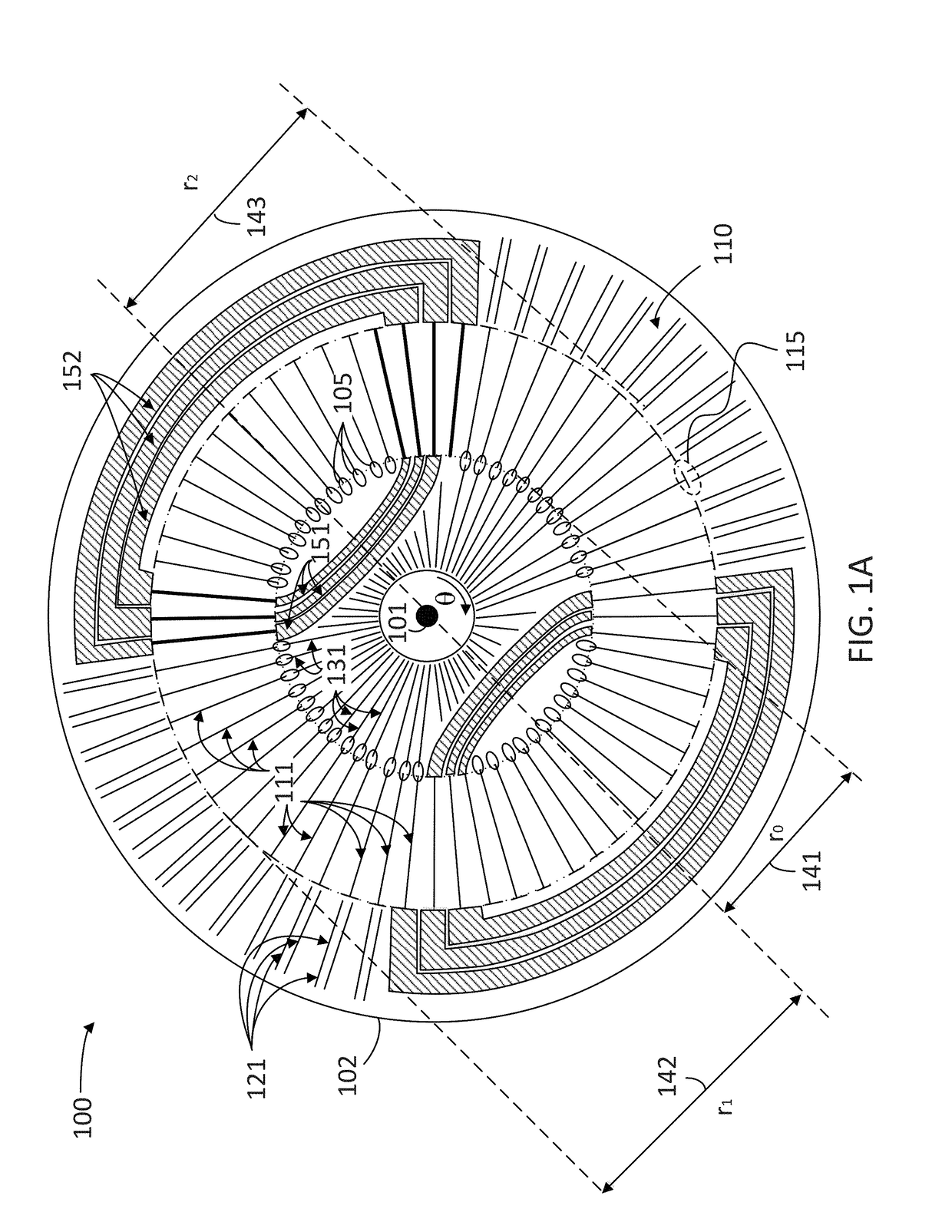
[0019]FIG. 1A illustrates a plan view of a stator 100 including a planar composite structure (PCS) 110 having at least one dielectric layer and a plurality of conductive elements 111, 121, and 131, according to some embodiments. Conductive elements 111, 121 and 131 may be part of a thermal mit...


PUM


Abstract

A stator for a motor or generator including a planar composite structure (PCS) having at least one dielectric layer and a plurality of conductive layers is provided. The stator includes first conductive elements extending radially to a distance r1 from a center of, and disposed angularly on, the PCS. Each first conductive element includes a preferred termination structure to connect with at least one of a plurality of second conductive elements extending radially from a radius r2 from the center of, and disposed angularly on, the PCS.

Description

CROSS-REFERENCE TO RELATED APPLICATIONS[0001]This application is a continuation of and claims the benefit under 35 U.S.C. § 120 to U.S. patent application Ser. No. 15 / 852,972, entitled PLANAR COMPOSITE STRUCTURES AND ASSEMBLIES FOR AXIAL FLUX MOTORS AND GENERATORS, filed Dec. 22, 2017, and published as U.S. Patent Application Publication No. 2018-0138770 A1, which claims the benefit under 35 U.S.C. § 119(e) of U.S. Provisional Application Ser. No. 62 / 530,552, entitled STRUCTURES AND METHODS OF STACKING SUBASSEMBLIES IN PLANAR COMPOSITE STATORS TO OBTAIN HIGHER WORKING VOLTAGES, filed Jul. 10, 2017, and which is also a continuation-in-part of and claims the benefit under 35 U.S.C. § 120 to U.S. patent application Ser. No. 15 / 611,359, entitled STRUCTURES AND METHODS FOR CONTROLLING LOSSES IN PRINTED CIRCUIT BOARDS, filed Jun. 1, 2017, and now U.S. Pat. No. 9,859,763, which (A) is a continuation-in-part of and claims the benefit under 35 U.S.C. § 120 to U.S. patent application Ser. No....

Claims


Application Information

Patent Timeline
Patent Type & Authority Patents(United States)
IPC IPC(8): H01K3/26H02K3/50H02K1/27H02K3/26H05K1/02H02K21/24H02K1/18
CPCH02K3/26H02K1/182H05K1/0298H02K3/50H02K21/24H02K1/27H05K1/165H05K2201/09227
Inventor SHAW, STEVEN ROBERT
Owner E CIRCUIT MOTORS INC
Why Eureka
Try Eureka