Closure device

Active Publication Date: 2019-02-26
FIDLOCK GMBH
View PDF26 Cites 10 Cited by
  • Summary
  • Abstract
  • Description
  • Claims
  • Application Information

AI Technical Summary

Benefits of technology

[0019]In another embodiment, the first closure member comprises a blocking element which, in the closed position, faces a back face of the second closure member. The back face herein faces in a direction opposite to the engagement direction and lies opposite the front face on the base of the first closure member. The blocking element is constituted to prevent the second locking protrusion from moving out of its engagement with the first locking protrusion in the direction opposite the engagement direction when the closure device is in its closed position. The blocking element hence serves to prevent the second closure member to move out of engagement with the first closure member in a direction opposite the engagement direction such that the second closure member cannot be released without further ado by displacing it against the engagement direction.
[0020]The provision of the blocking element may provide for a particularly strong closure device which is suitable to carry large loads as it is for example required for a safety closure such as for a motorbike helmet which must not open even if excessively large loads, vibrating loads or loads from different directions act onto the closure de

Problems solved by technology

The closure device of U.S. Pat. No. 5,664,298 serves as a closu

Method used


Image

  • Closure device
  • Closure device
  • Closure device

Examples


Embodiment Construction

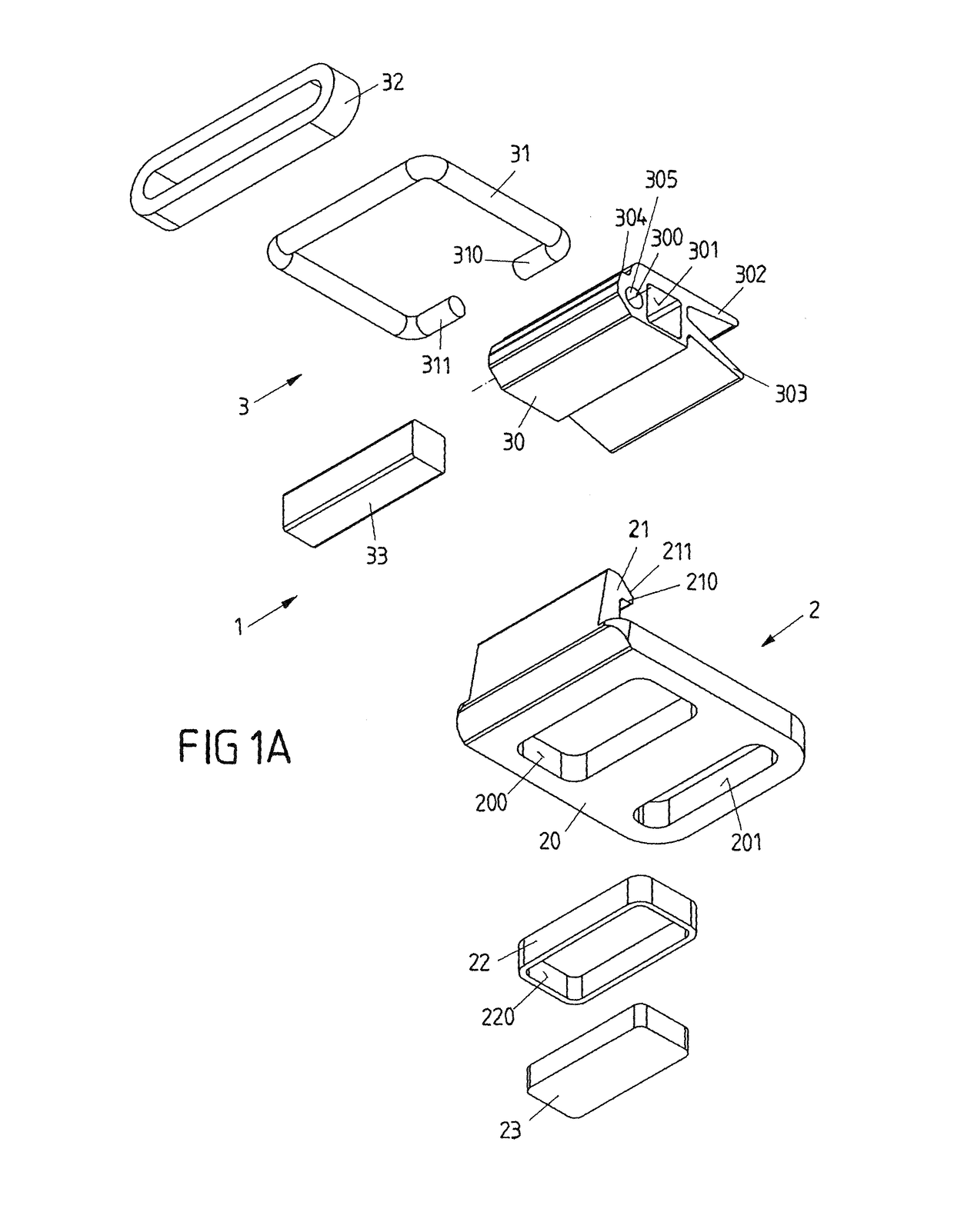
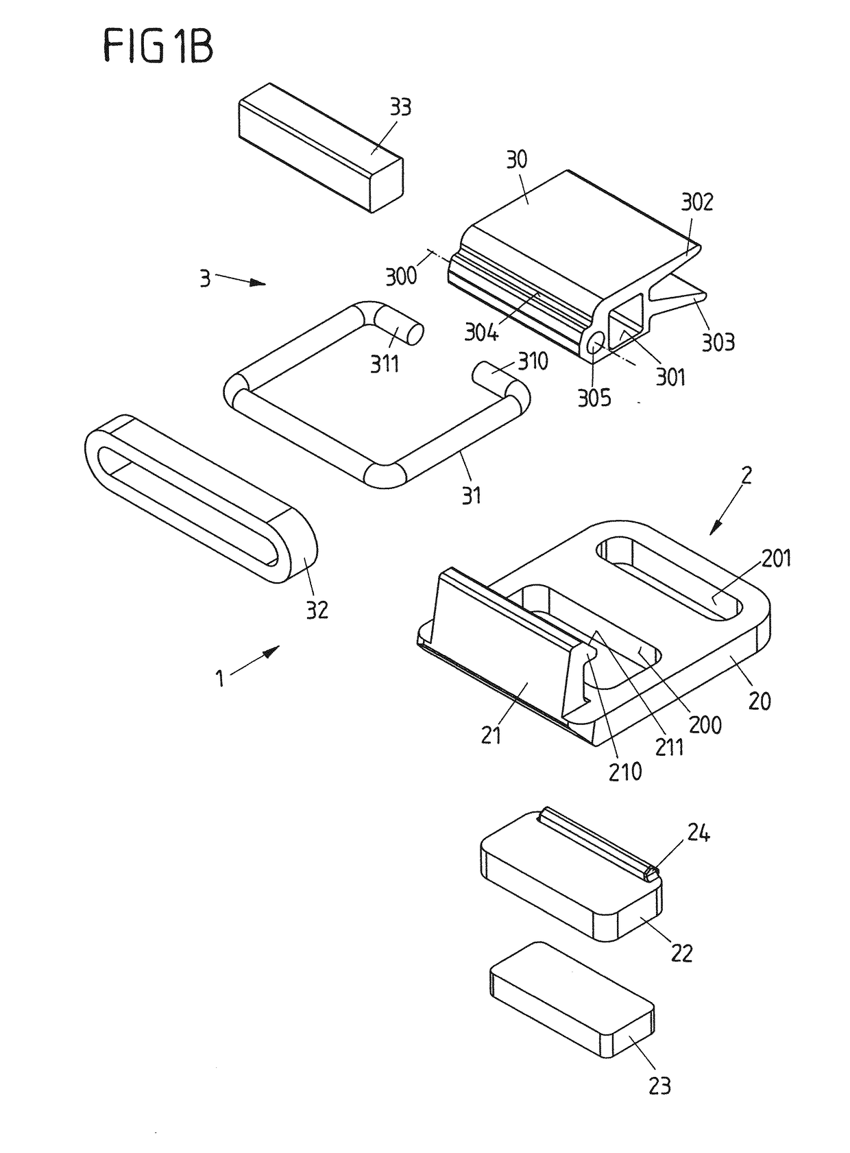
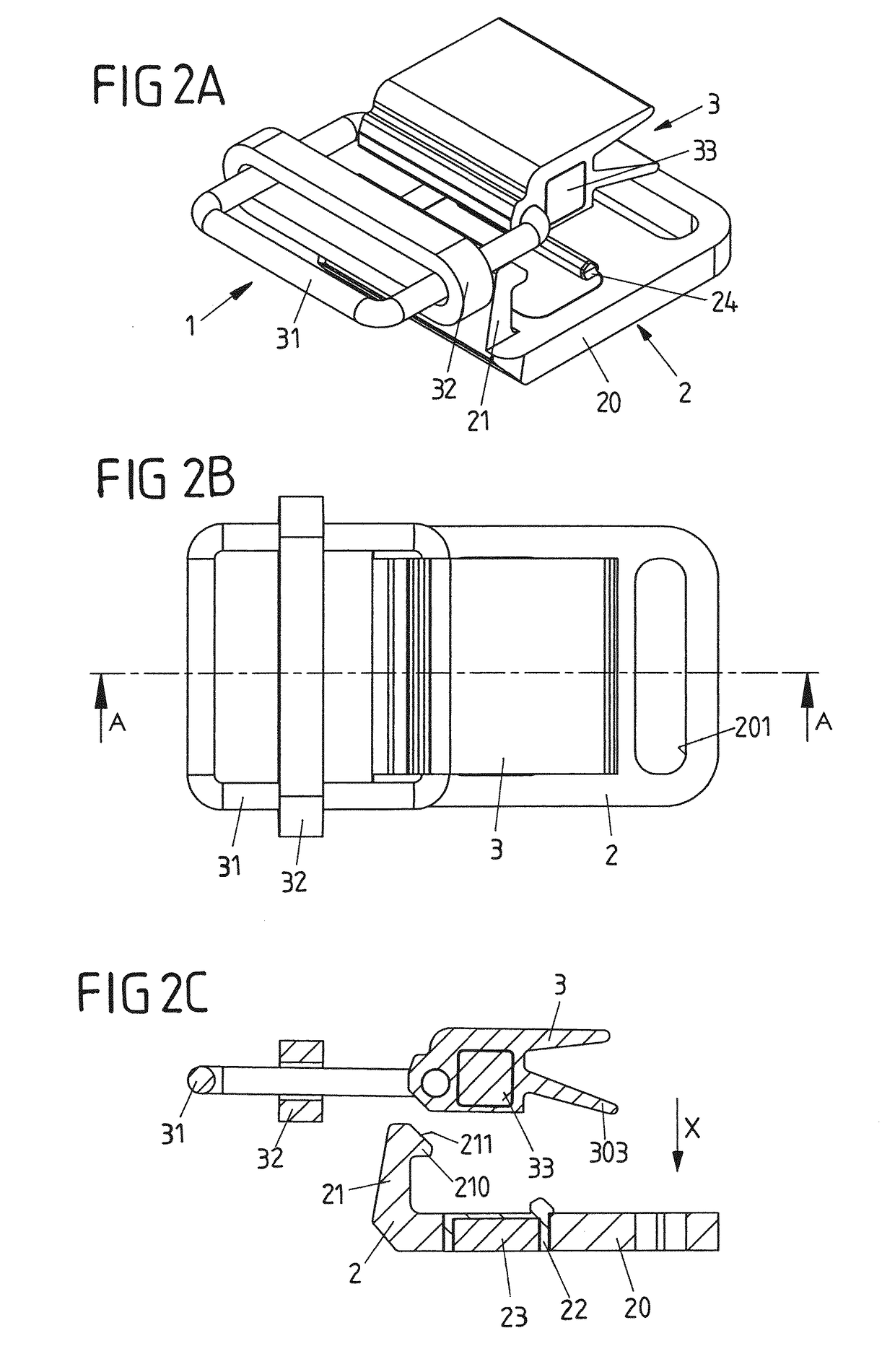
[0075]According to FIGS. 1A, 1B to FIGS. 7A to 7C subsequently a first embodiment of a closure device 1 shall be explained comprising a first closure member 2 and a second closure member 3.

[0076]Herein, the first closure member 2 comprises a base 20 carrying a locking element 21 with a locking protrusion 210. The locking element 21 is rigidly attached to the base 20, extends from the base 20 and carries the rigid locking protrusion 210. The base 20 and the locking element 21 with the locking protrusion 210 may beneficially be formed in one piece from plastics or metal.

[0077]The base 20 comprises an opening 200 into which a magnet housing 22 receiving, in a reception opening 220, a magnetic member 23 in the shape of a magnet or a magnetic armature is inserted such that the magnetic member 23 is fixedly held on the base 20. The base 20 furthermore has a belt receptacle 201 to which a belt can be attached.

[0078]A second closure member 3 comprises a locking part 30 carrying a locking pr...


PUM


Abstract

A closure device for releasably connecting two parts with each other includes a first closure member and a second closure member attachable to the first closure member and in a closed position is held on the first closure member. The second closure member has a rigid second locking protrusion, wherein the second locking protrusion can be brought into engagement with the first locking protrusion in an engagement direction and in the closed position engages the first locking protrusion in a positive locking manner. The first closure member includes a first magnetic member and the second closure member includes a second magnetic member, the first magnetic member and the second magnetic member being constituted to magnetically attract each other when the second closure member is attached to the first closure member for closing the closure device.

Description

CROSS-REFERENCE TO RELATED APPLICATIONS[0001]This application is the United States national phase of International Application No. PCT / EP2013 / 060762 filed May 24, 2013, and claims priority to European Patent Application No. 13167140.6 filed May 8, 2013, the disclosures of which are hereby incorporated in their entirety by reference.BACKGROUND OF THE INVENTIONField of the Invention[0002]The invention relates to a closure device for releasably connecting two parts with each other.[0003]A closure device of this kind comprises a first closure member having a rigid first locking protrusion and a second closure member having a rigid second locking protrusion. The second closure member is attachable to the first closure member and in a closed position is held on the first closure member such that parts connected with the closure members are connected with each other. For closing the closure device the second locking protrusion can be brought into engagement with the first locking protrusio...

Claims


Application Information

Patent Timeline
IPC IPC(8): A44B11/25A44B99/00F16B1/00
CPCA44B99/00A44B11/2588F16B1/00Y10T24/32A44D2203/00F16B2001/0035F16B2200/83
Inventor FIEDLER, JOACHIMTUCHOLKE, ARTUR
Owner FIDLOCK GMBH
Why Eureka
Try Eureka