Angle-adjustable lamp

a lamp and angle adjustment technology, applied in the field of adjustable lamps, can solve the problems of wasting time and money, affecting the development of the modern lighting industry, so as to achieve the effect of avoiding waste and high adaptability

Active Publication Date: 2019-02-26
NINGBO YAMAO OPTOELECTRONICS CO LTD
View PDF4 Cites 2 Cited by
  • Summary
  • Abstract
  • Description
  • Claims
  • Application Information

AI Technical Summary

Benefits of technology

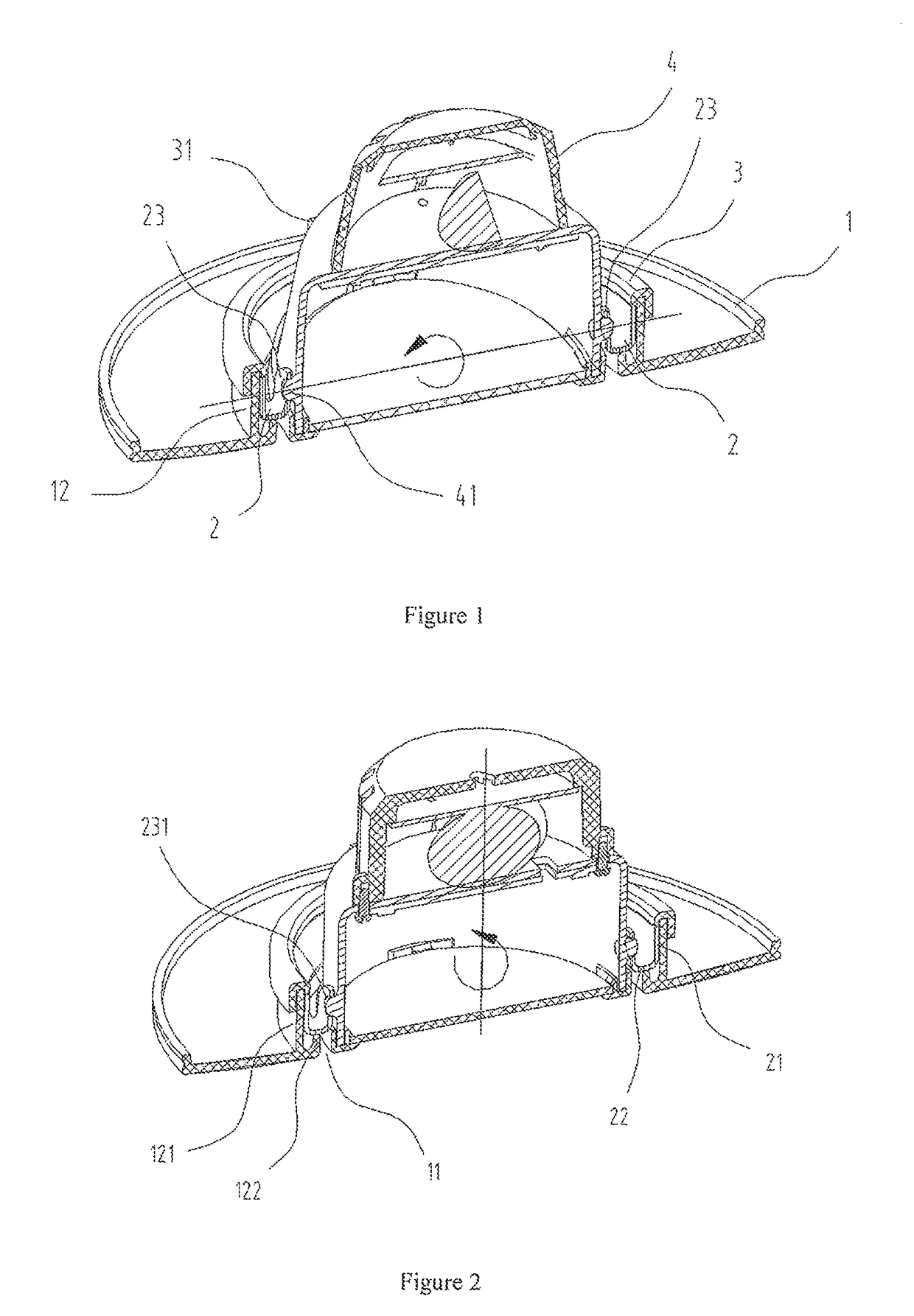
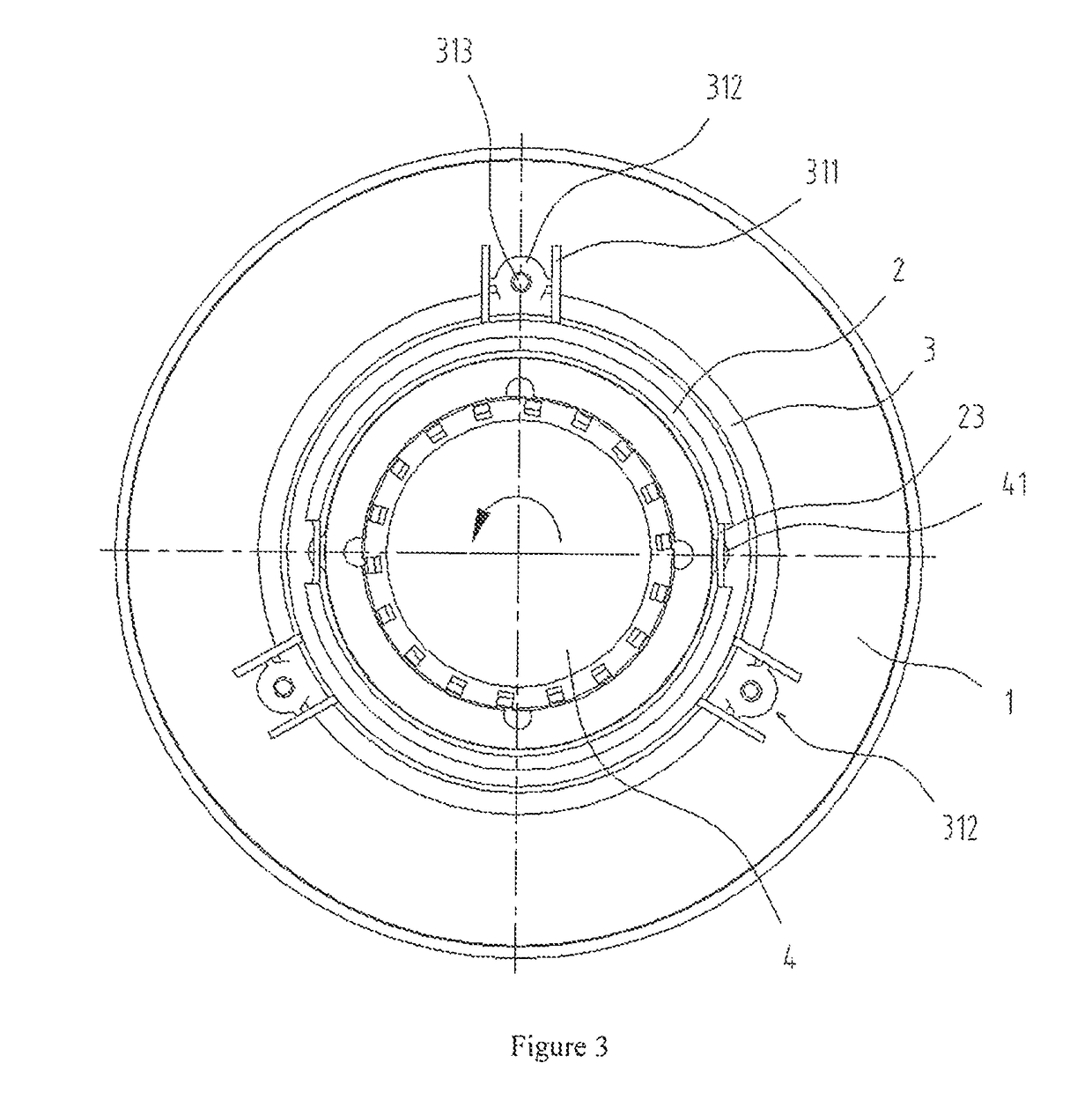
[0008]In view of the above problems in the prior art, the invention is now intended to provide an angle-adjustable lamp, which sets a lamp holder which can transform a variety of angles and match with an adjustable lamp, and its transformation angle is great hereinto. Therefore, the lamp can be applied to different illumination environment and has high adaptability, thus avoiding the waste resulting from re-installation of lamps.
[0022]The positive effects of the above technical solutions are: 1. by arranging the round lamp hole to facilitate the rotation of the lamp body, the range of rotation direction is widened; 2. the rotating ring is embedded inside the protrusion of the fixing socket and the movement of lamp body is arranged on the rotating ring, so the rotating ring can rotate around the axis of the lamp hole in the fixing socket and the angular restriction becomes smaller; 3. a fixing ring is reversely arranged on the protrusion, thus preventing the raising and falling motion of the rotating ring effectively and having better stability; 4. the lamp body is provided with the hemispherical protruded blocks, thus improving the rotation characteristics of lamp body in the rotating ring, having less restrictions, and becoming easy to disassemble and maintain; 5. a by arranging a plurality of limits, the lamp body is effectively prevented from rotating out of the fixing socket and damaging the lamp body , thus having a higher security.

Problems solved by technology

If you need to change the lighting area, you need to relocate the fixing socket or re-install new lamps for lightening, the former is not only a waste of time and effort but also easy to damage the lamp, the latter wastes time and its cost is relatively high, and is not good for the modern lighting industry development.
In conclusion, the problem of current lamps on the market is that it cannot change the direction of lighting so that it results in waste.

Method used


Image

  • Angle-adjustable lamp
  • Angle-adjustable lamp

Examples


Embodiment Construction

[0028]The present invention will now be described more fully hereinafter with reference to the accompanying drawings, in which exemplary embodiments of the invention are shown. This invention may, however, be embodied in many different forms and should not be construed as limited to the embodiments set forth herein. Rather, these embodiments are provided so that this disclosure will be thorough and complete, and will fully convey the scope of the invention to those skilled in the art. Like reference numerals refer to like elements throughout.

[0029]The terminology used herein is for the purpose of describing particular embodiments only and is not intended to be limiting of the invention. As used herein, the singular forms “a”, “an” and “the” are intended to include the plural forms as well, unless the context clearly indicates otherwise. It will be further understood that the terms “comprises” and / or “comprising,” or “includes” and / or “including” or “has” and / or “having” when used he...


PUM


Abstract

The invention provides an angle-adjustable lamp and relates to the technical field of lighting. An angle-adjustable lamp comprises a fixing socket which is provided with a lamp hole, a rotating ring which rotates inside the protrusion of the outer edge of lamp hole, a fixing ring reversely sleeved on the protrusion and the lamp body connected to the rotating ring through two protrusions; by arranging the annular protrusion in the rim of the lamp hole and embedding rotating ring inside the protrusion, the rotation of the rotating ring along the center of lamp hole is ensured, and the limitation of rotation angle of lamp is extended; by arranging the annular fixing ring in the protrusion, raising and falling motion of rotating ring can be prevented effectively, therefore, the rotation process becomes more smooth.

Description

CROSS-REFERENCE TO RELATED APPLICATIONS[0001]The present application claims priority to and the benefit of Chinese Patent Application No. CN 201710071787.4, filed on Feb. 9, 2017, the entire content of which is incorporated herein by reference.BACKGROUND OF THE INVENTION[0002]1. Field of the Invention[0003]The invention relates to the field of illuminating lamp, more specifically, to an angle-adjustable lamp.[0004]2. Description of the Related Art[0005]Lamps have become an important part and a necessary lighting tool in people's life, so there are more and more researches about lamps.[0006]Due to the difference of working environments of lamps as well as the requirements of lightening, structural requirements of lamp has been increased accordingly to meet lightening needs of different uses. The existing lamps mainly comprise a fixing socket and a lamp body, and generally, the fixing socket is fixedly arranged within the area requiring lightening, and the lamp body is fixedly arrange...

Claims


Application Information

Patent Timeline
Patent Type & Authority Patents(United States)
IPC IPC(8): F21V17/02F21V19/00F21V17/12
CPCF21V17/02F21V17/12F21V19/006F21S8/00F21V14/02F21V21/14F21S8/02
Inventor XU, QILIFANG, HUZHOU, YINYONG
Owner NINGBO YAMAO OPTOELECTRONICS CO LTD
Why Eureka
Try Eureka