
Glass light guide plate and back light unit having the same

a technology of back light unit and light guide plate, which is applied in the direction of optical light guide, instruments, optics, etc., can solve the problems of limited arrangement of plastic light guide plate, low light transmittance of plate, and additional support structure, so as to reduce the thickness of light guide plate, improve the bonding force of light guide pattern, and minimize performance deterioration. effect of phenomenon

Active Publication Date: 2019-03-19
LG DISPLAY CO LTD
View PDF11 Cites 0 Cited by
  • Summary
  • Abstract
  • Description
  • Claims
  • Application Information

AI Technical Summary

Benefits of technology

The present invention provides a new method for manufacturing a glass light guide plate for a back light unit of a display device. The method manages the shape and position of bubbles in the bare glass of the guide plate to prevent performance deterioration caused by the bubbles. The invention also minimizes the spacing gap between the guide plate and the light source to reduce light leakage and hot spot phenomena. By optimizing the ink used to form light guide patterns, the bonding force and strength of the patterns is improved. These technical effects can provide a thinner display device and minimize the problem of glass material to reduce the thickness of the light guide plate.

Problems solved by technology

In addition, the plastic light guide plate has disadvantages in that, due to a large thermal expansion coefficient and a high moisture-swelling property, the plastic light guide plate is limited in arrangement with a light source part, and requires an additional support structure.
However, the glass light guide plate has problems in that the glass light guide plate has a low light transmittance as compared with the plastic light guide plate, and in particular, when a bare glass is fabricated for manufacturing a light guide plate, bubbles are generated inside the bare glass, and the performance of the light guide plate is deteriorated by the bubbles.
In addition, due to the difference in material between the plastic and the glass, various disadvantages have occurred when the method of forming a light guide pattern, which is formed on one side of a light guide plate, is equally applied to the plastic light guide plate and the glass light guide plate.

Method used


Image

  • Glass light guide plate and back light unit having the same
  • Glass light guide plate and back light unit having the same
  • Glass light guide plate and back light unit having the same

Examples


Embodiment Construction

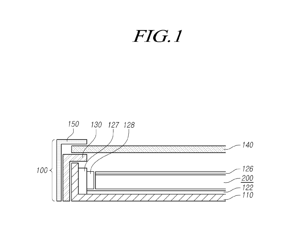
[0033]Hereinafter, some embodiments of the present invention will be described in detail with reference to the accompanying illustrative drawings. In designating elements of the drawings by reference numerals, the same elements will be designated by the same reference numerals although they are shown in different drawings. Further, in the following description of the present invention, a detailed description of known functions and configurations incorporated herein will be omitted when it may make the subject matter of the present invention rather unclear.

[0034]In addition, terms, such as first, second, A, B, (a), (b) or the like may be used herein when describing components of the present invention. Each of these terminologies is not used to define an essence, order or sequence of a corresponding component but used merely to distinguish the corresponding component from other component(s). In the case that it is described that a certain structural element “is connected to”, “is coup...


PUM


Abstract

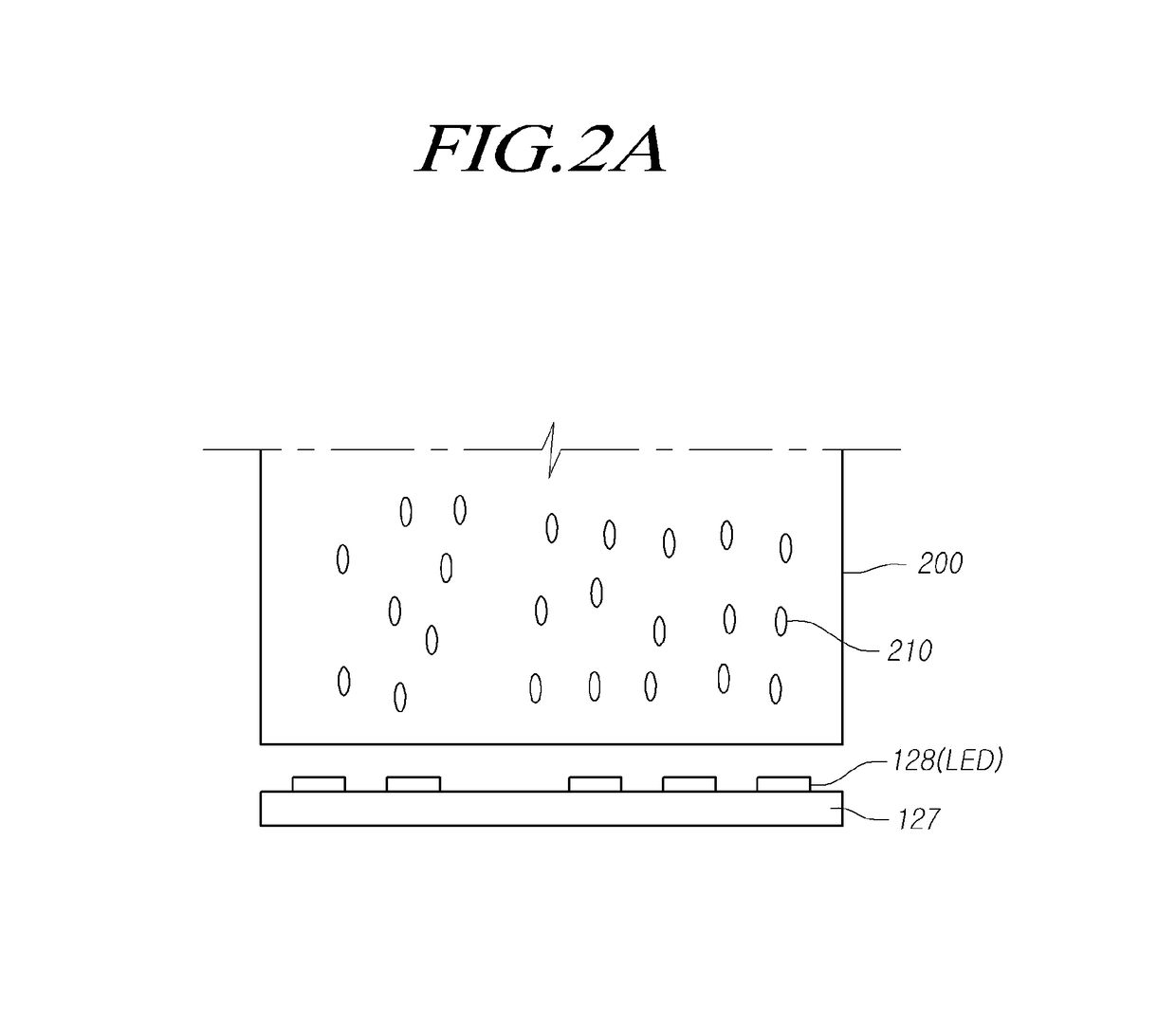
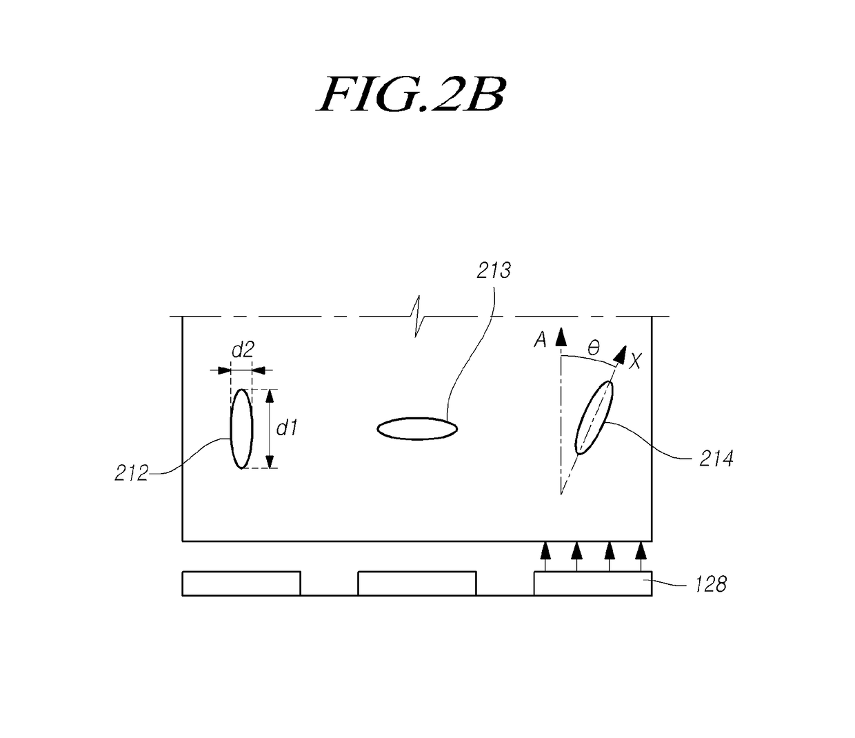
Discussed is a glass light guide plate that is used in a back light unit of a display device. Some features of the glass light guide plate for the back light unit can be improved by optimizing a relationship between a direction of a bubble inside the glass light guide plate and a light source, the sizes of the bubble and a light guide pattern, and so on, and by optimizing an arrangement density of light guide patterns in each region, a kind of light guide pattern ink (IR-curable ink), a curing condition, a refractive index, and so on to be suitable for the material of the glass light guide plate.

Description

CROSS REFERENCE TO RELATED APPLICATION[0001]This application claims priority from Korean Patent Application No. 10-2015-0151497, filed on Oct. 30, 2015, which is hereby incorporated by reference for all purposes as if fully set forth herein.BACKGROUND OF THE INVENTIONField of the Invention[0002]The present invention relates to a back light unit for a display device and a glass light guide plate included therein. More particularly, the present invention relates to a technology for solving a problem of performance deterioration caused by bubbles in a bare glass, and optimizing a material of an ink for light guide patterns (hereinafter, referred to as a “light guide pattern ink), and an arrangement and curing method of light guide patterns according to the use of a glass material.Description of the Related Art[0003]According to the development of an information society, demands for display devices for displaying images have increased in various types. Recently, various display devices,...

Claims


Application Information

Patent Timeline
Patent Type & Authority Patents(United States)
IPC IPC(8): F21V8/00
CPCG02B6/0036G02B6/0061G02B6/0041G02B6/0055G02B1/00G02B6/0033G02B6/0065G02F1/133606
Inventor MOON, CHANGYULJEONG, YOUNGHUNYANG, KIYONGPARK, SEHYUN
Owner LG DISPLAY CO LTD
Learn More