Localized synthesis and self-assembly of nanostructures
- Summary
- Abstract
- Description
- Claims
- Application Information
AI Technical Summary
Benefits of technology
Problems solved by technology
Method used
Image
Examples
example 1
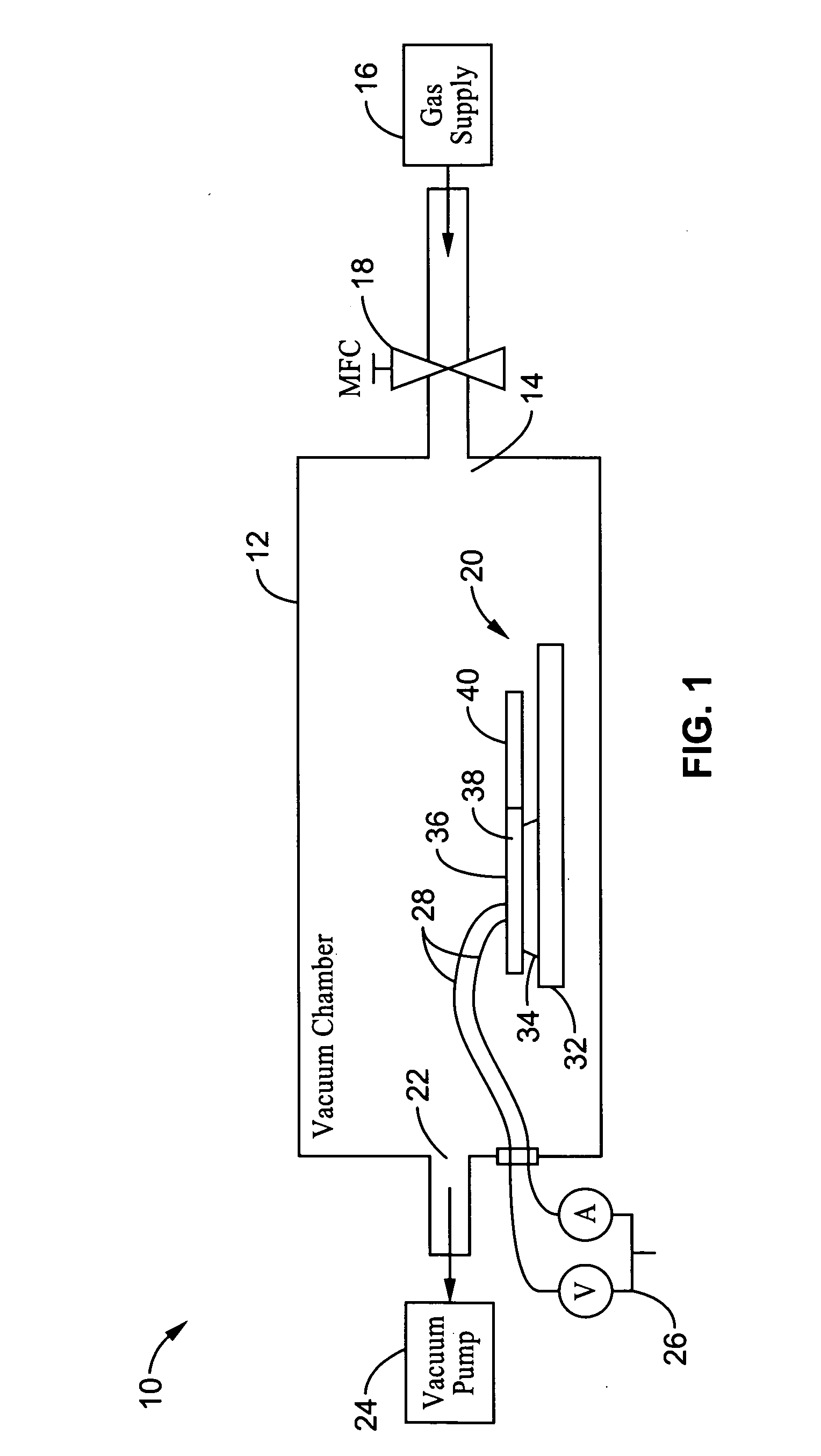
[0066] Two types of suspended microelectromechanical systems (MEMS) structures were fabricated to serve as localized microresistive heaters for the synthesis processes: (i) polysilicon microstructures using a standard surface micromachining process, and (ii) bulk-etched single crystal silicon (SCS) microstructures based on a silicon on insulator (SOI) wafer. The synthesis processes were carried out in a growth chamber 10 having a vacuum chamber 12 at room temperature as shown schematically in FIG. 1. A treatment gas is supplied to the vacuum chamber 12 at inlet 14 via gas supply 16, and is controlled by mass flow controller 18. Microstructure 20 is positioned inside the vacuum chamber 12 and is connected to power supply 26 via leads 28. Vacuum pump 24 draws gas out of the chamber via outlet 22.
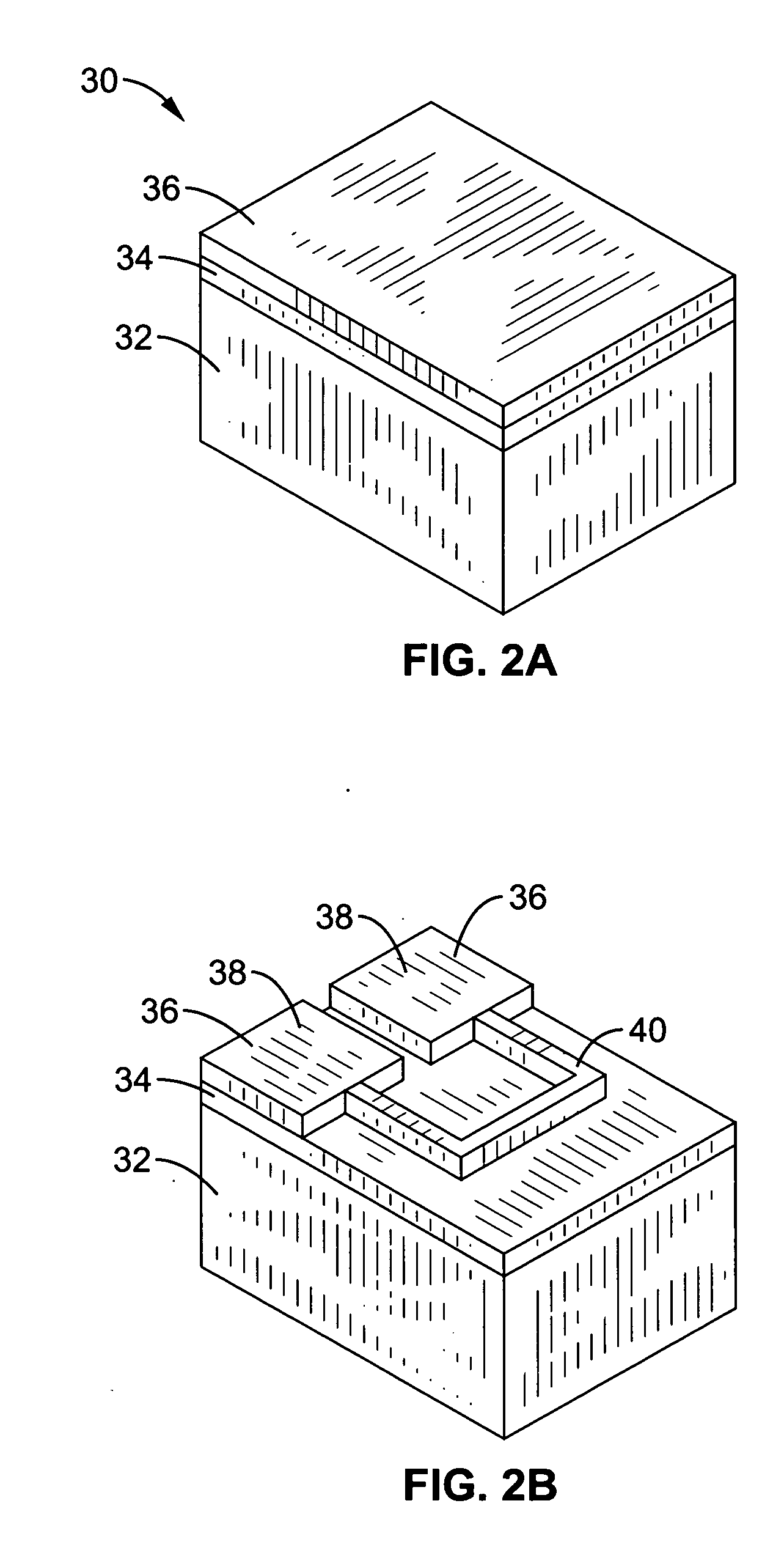
[0067]FIGS. 2A through 2G illustrate the fabrication of microstructure 20 and use in growth chamber 10 for generation of nanostructures. FIG. 2A illustrates an initial three-layer wafer 30 us...
example 2
[0087] For nanotube synthesis, the same method and phenomena described above with respect to nanowire synthesis are employed. In this embodiment, a thin metal layer 42 was evaporated over the entire chip to serve as a the catalyst for growth. A mixture of approximately 5 nm nickel, iron, or Ni—Fe (80% to 20% by weight) was used as the catalyst, with higher growth rates occurring when iron was present (e.g., see FIG. 2D). After wirebonding for electrical connectivity, the microstructures were placed into a room temperature vacuum chamber (e.g., see, FIG. 2E). The organic vapor phase, acetylene (C2H2), was introduced at 245 mTorr to supply carbon and the microstructure was heated to initiate nanotube synthesis (e.g., see FIG. 2E). With the acetylene pressure constant at 245 mTorr, growth occurred at 0.25 μm / min at optimal temperature locations. Note that growth rate may also depend on the pressure. Note also that carbon nanotube (CNT) growth requires higher temperatures for the synthe...
example 3
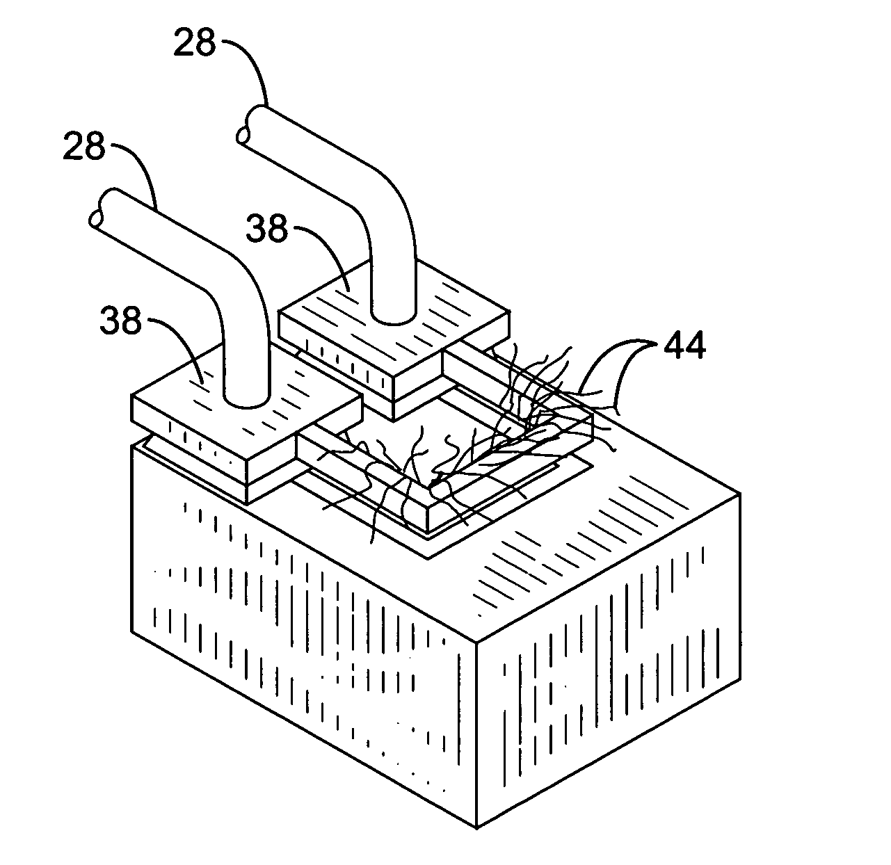
[0098] We also demonstrated that orientation of nanotubes 76 is a function of the electric field E as shown in FIGS. 13A-B. The bottom right side 80 of this “U-shaped” microstructure 40 was taken to approximately 7V, while the bottom left side 82 was grounded, yielding an electric field of approximately 0.12 V / μm in the region where the longest growth occurred. This region is further detailed in expanded view of FIG. 13B which shows the CNT from outside the microstructure 40 curving with the electric field E. This electric field is weaker than desirable for oriented CNT growth, but shows that the electric field due to the synthesis process alone can be used to orient the tubes. The addition of additional electric field, by increasing the potential difference between nearby microstructures, will enhance this effect.
[0099] It will be appreciated that assembly is probably the most difficult task in any nanostructure integration process. To facilitate assembly, the present invention us...
PUM
| Property | Measurement | Unit |
|---|---|---|
| Temperature | aaaaa | aaaaa |
| Electric potential / voltage | aaaaa | aaaaa |
| Microstructure | aaaaa | aaaaa |
Abstract
Description
Claims
Application Information
 - R&D
- Intellectual Property
- Life Sciences
- Materials
- Tech Scout
- Unparalleled Data Quality
- Higher Quality Content
- 60% Fewer Hallucinations
Browse by: Latest US Patents, China's latest patents, Technical Efficacy Thesaurus, Application Domain, Technology Topic, Popular Technical Reports.
© 2025 PatSnap. All rights reserved.Legal|Privacy policy|Modern Slavery Act Transparency Statement|Sitemap|About US| Contact US: help@patsnap.com


