Flight control method and unmanned unmannered aerial vehicle

a technology of flight control and unmanned aerial vehicles, applied in the direction of process and machine control, using reradiation, instruments, etc., can solve the problems of increasing the chance and the foregoing technique is susceptible to further improvement, so as to achieve the effect of reducing the risk of collision between unmanned aerial vehicles

Active Publication Date: 2019-03-19
PANASONIC INTELLECTUAL PROPERTY CORP OF AMERICA
View PDF20 Cites 1 Cited by
  • Summary
  • Abstract
  • Description
  • Claims
  • Application Information

AI Technical Summary

Benefits of technology

[0007]According to an embodiment of the present disclosure, the risk of collision between unmanned aerial vehicles may further be reduced.

Problems solved by technology

When many unmanned aerial vehicles fly in the sky, the chance of a collision between unmanned aerial vehicles is increased.
However, the foregoing technique is susceptible to further improvement.

Method used


Image

  • Flight control method and unmanned unmannered aerial vehicle
  • Flight control method and unmanned unmannered aerial vehicle
  • Flight control method and unmanned unmannered aerial vehicle

Examples


first embodiment

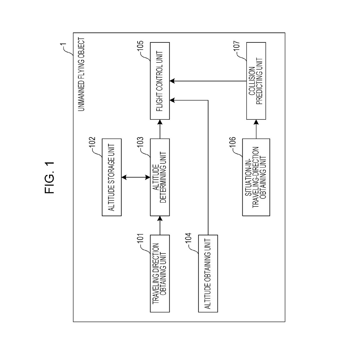
[0048]FIG. 1 is a diagram illustrating the configuration of an unmanned aerial vehicle according to a first embodiment of the present disclosure.

[0049]An unmanned aerial vehicle 1 flies autonomously in accordance with a flight route generated in advance. The unmanned aerial vehicle 1 is equipped with a plurality of propellers and moves forward, backward, leftward, rightward, upward, and downward, with the rotation rate of each propeller being controlled. The unmanned aerial vehicle 1 flies autonomously along a flight route generated in advance while obtaining its current position by using the Global Positioning System (GPS), which is not illustrated. The flight route is generated by a flight route generation apparatus, for example, a smartphone, a tablet computer, or a personal computer. The unmanned aerial vehicle 1 receives the flight route generated by the flight route generation apparatus.

[0050]The unmanned aerial vehicle 1 illustrated in FIG. 1 includes a traveling direction ob...

second embodiment

[0086]Next, a description will be given of an unmanned aerial vehicle according to a second embodiment of the present disclosure. An unmanned aerial vehicle is susceptible to wind when the weight of its body is low. Accordingly, in the second embodiment, a flight altitude range is changed in accordance with the weight of an unmanned aerial vehicle.

[0087]FIG. 5 is a diagram illustrating the configuration of an unmanned aerial vehicle according to the second embodiment of the present disclosure. The unmanned aerial vehicle 11 illustrated in FIG. 5 includes a traveling direction obtaining unit 101, an altitude storage unit 102, an altitude obtaining unit 104, a flight control unit 105, a situation-in-traveling-direction obtaining unit 106, a collision predicting unit 107, a weight obtaining unit 108, and an altitude determining unit 1031. In the unmanned aerial vehicle 11 according to the second embodiment, the same components as those in the unmanned aerial vehicle 1 according to the ...

third embodiment

[0101]Next, a description will be given of an unmanned aerial vehicle according to a third embodiment of the present disclosure. If there is a tall structure such as a building around an unmanned aerial vehicle and if the unmanned aerial vehicle flies low, the chance of a collision between the unmanned aerial vehicle and the structure is increased. Accordingly, in the third embodiment, a flight altitude range is changed in accordance with the height of a structure around a current position of an unmanned aerial vehicle.

[0102]FIG. 7 is a diagram illustrating the configuration of an unmanned aerial vehicle according to the third embodiment of the present disclosure. The unmanned aerial vehicle 12 illustrated in FIG. 7 includes a traveling direction obtaining unit 101, an altitude storage unit 102, an altitude obtaining unit 104, a flight control unit 105, a situation-in-traveling-direction obtaining unit 106, a collision predicting unit 107, a structure information obtaining unit 109,...


PUM


Abstract

A method for controlling an aerial vehicle includes determining a direction in which the aerial vehicle is traveling; determining, with reference to a table, an altitude range which corresponds to the determined direction and within which the aerial vehicle is caused to fly, the table indicating correspondences between directions in which the aerial vehicle is traveling and altitude ranges within which the aerial vehicle is to fly; obtaining, from an altimeter, a first altitude, which is a current altitude, at which the aerial vehicle is flying; determining whether the first altitude is included in the determined altitude range; and if it is determined that the first altitude is not included in the determined altitude range, changing an altitude at which the aerial vehicle is caused to fly from the first altitude to a second altitude included in the determined altitude range.

Description

BACKGROUND1. Technical Field[0001]The present disclosure relates to a flight control method for controlling flight of an unmanned aerial vehicle and to an unmanned aerial vehicle.2. Description of the Related Art[0002]In recent years, compact unmanned aerial vehicles that fly autonomously have been developed, and inspection of infrastructure or transportation of goods by using unmanned aerial vehicles has been considered. Such an unmanned aerial vehicle is equipped with a plurality of propellers and is able to fly freely in the sky or autonomously along a predetermined flight route, with the rotation rate of each propeller being controlled.[0003]When many unmanned aerial vehicles fly in the sky, the chance of a collision between unmanned aerial vehicles is increased. Thus, a technique for preventing a collision between unmanned aerial vehicles has been developed.SUMMARY[0004]However, the foregoing technique is susceptible to further improvement.[0005]In one general aspect, the techn...

Claims


Application Information

Patent Timeline
Patent Type & Authority Patents(United States)
IPC IPC(8): G05D1/04G08G5/00G05D1/10G01S19/13B64D47/08G08G5/04B64C39/02
CPCG08G5/045B64C39/024B64D47/08G01S19/13G05D1/042G05D1/104G08G5/0021G08G5/0052G08G5/0069G08G5/0078G08G5/006B64C2201/145B64C2201/108B64C2201/127G01S19/393G01S19/15B64U2101/60B64U2101/30B64U2201/104G01S17/00B64U30/20
Inventor UMETANI, HIDEOTAKEUCHI, KAZUMA
Owner PANASONIC INTELLECTUAL PROPERTY CORP OF AMERICA
Why Eureka
Try Eureka