Fan module

a technology of fan module and fan frame, which is applied in the direction of machines/engines, mechanical equipment, liquid fuel engines, etc., can solve the problems of difficult effective avoidance of tilting, and achieve the effect of minimizing the risk of collision between the rotating fan and the fan fram

Inactive Publication Date: 2013-04-18
ROBERT BOSCH GMBH
View PDF7 Cites 2 Cited by
  • Summary
  • Abstract
  • Description
  • Claims
  • Application Information

AI Technical Summary

Benefits of technology

[0004]The object of the present invention is therefore to make available a fan in which the risk of collision between the rotating fan and the fan frame can be minimized even when strong centrifugal forces occur, with the result that the fan can be mounted at the smallest possible radial distance from adjacent components, such as, for example, a fan frame.

Problems solved by technology

Owing to the narrow installation spaces and the peripheral conditions for conducting the air flow, it is, however, difficult to effectively avoid tilting.

Method used


Image

  • Fan module
  • Fan module
  • Fan module

Examples


Embodiment Construction

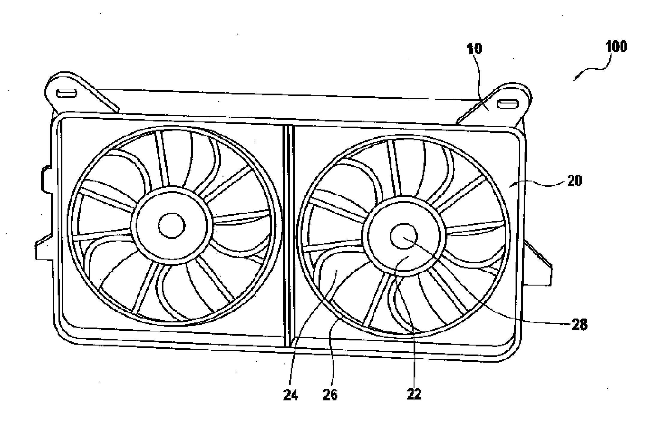
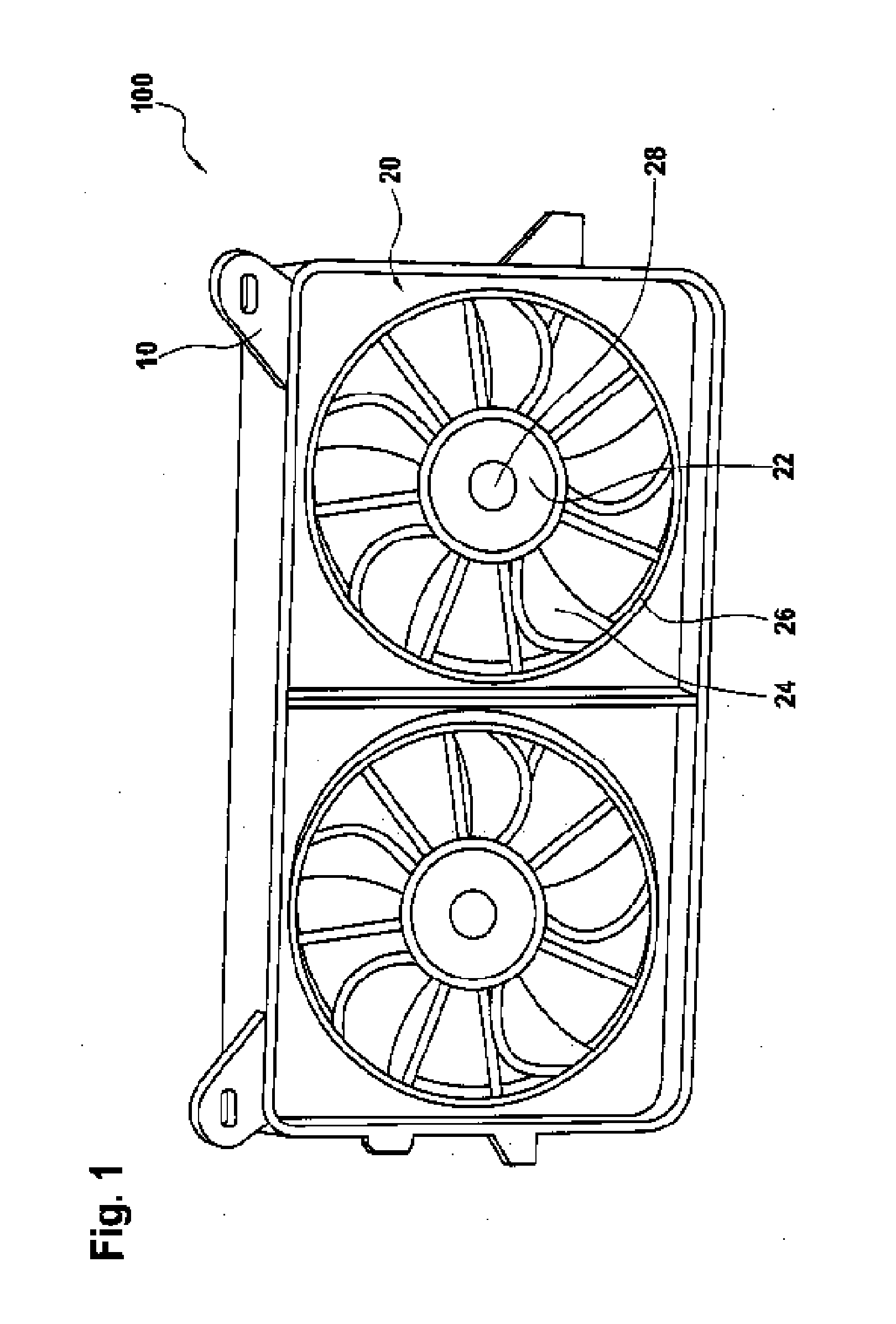
[0025]As shown in FIG. 1, a cooling module 100 comprises a fan 20, which is rotatably mounted in a fan frame 10. The cooling module 100 may, for example, be mounted in the engine cavity of a motor vehicle. The fan 20 comprises a fan hub 22, a multiplicity of fan blades 24 and a fan belt 26.

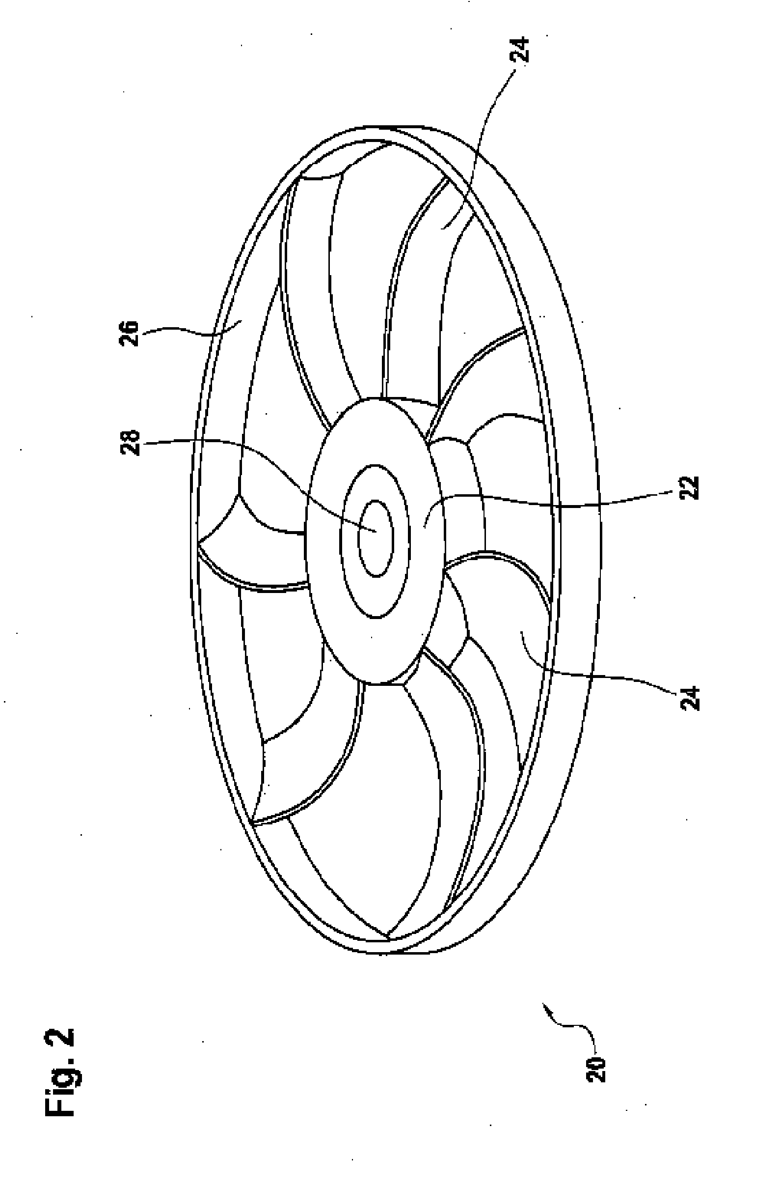
[0026]As illustrated in FIG. 2, the fan blades 24 are arranged radially on the outside of the fan hub 22, and the fan belt 26 connects the respective radially outer ends of the fan blades 24. A shaft bushing 28, by means of which the fan hub 22 is rotatably mounted on a shaft (not shown), is arranged radially on the inside of the fan hub 22. The fan is driven by means of an electric motor, wherein the stator is fixedly mounted on the shaft, and the outer rotor 30 (see FIGS. 6 and 7) is arranged in the fan hub 22 and is fixedly connected thereto.

[0027]FIG. 1 shows that there is a narrow gap between the fan belt 26 and the fan frame 10 in order to prevent a collision between the rotating fan 20 and ...


PUM


Abstract

A fan (20) comprises a fan hub (22), fan blades (24) which are mounted on the fan hub (22), and a drive motor having an outer rotor (30), wherein the outer rotor (30) is arranged inside the fan hub (22). The outer rotor (30) is arranged in the fan hub (22) in such a way that the outer rotor (30) is supported in a radially outward direction on the radial outer wall (36) of the fan hub (22), by means of cooling fins (32) which are formed integrally with the fan hub (22).

Description

BACKGROUND OF THE INVENTION[0001]The invention generally relates to a fan for use in motor vehicles.[0002]A cooling module is generally composed of an electric motor, a fan and a fan frame which surrounds the fan and the electric motor. The fan frame conducts the air which is sucked in by the fan and serves to attach the unit, composed of a fan and an electric motor, in, for example, an engine cavity of a motor vehicle.[0003]During cornering of the motor vehicle, a tilting moment is applied to the rotating fan owing to the centrifugal forces. When the fan hub is configured, care is taken to ensure that collisions cannot occur between the fan and the fan frame during cornering. This is generally implemented by means of a stiff fan hub which reduces the tilting of the fan. Owing to the narrow installation spaces and the peripheral conditions for conducting the air flow, it is, however, difficult to effectively avoid tilting.SUMMARY OF THE INVENTION[0004]The object of the present inven...

Claims


Application Information

Patent Timeline
Patent Type & Authority Applications(United States)
IPC IPC(8): H02K7/14
CPCH02K7/14H02K1/2786H02K9/06F01P3/04F04D29/329F04D29/522F04D29/646H02K15/12H02K1/2791
Inventor MAHFOUDH, SAMIRHANSEN, SEBASTIANARSLAN-HUERST, ASLI
Owner ROBERT BOSCH GMBH
Why Eureka
Try Eureka