Supercharge Your Innovation With Domain-Expert AI Agents!

Turbine engine vane arrangement having a plurality of interconnected vane arrangement segments

a technology of interconnected segments and turbine engines, which is applied in the direction of machines/engines, stators, liquid fuel engines, etc., can solve the problems of reducing the effectiveness of feather seals, and achieve the effect of substantially equal widths of base segments

Active Publication Date: 2019-03-26
RTX CORP
View PDF16 Cites 0 Cited by
  • Summary
  • Abstract
  • Description
  • Claims
  • Application Information

AI Technical Summary

Benefits of technology

This bonding approach significantly reduces fluid leakage by ensuring the inner and outer vane arrangement platforms deform and move as unitary bodies, maintaining seal effectiveness under varying conditions.

Problems solved by technology

Such deformations and / or movements may reduce the effectiveness of the feather seals and enable fluid leakage through the gaps.

Method used


Image

  • Turbine engine vane arrangement having a plurality of interconnected vane arrangement segments
  • Turbine engine vane arrangement having a plurality of interconnected vane arrangement segments
  • Turbine engine vane arrangement having a plurality of interconnected vane arrangement segments

Examples


Embodiment Construction

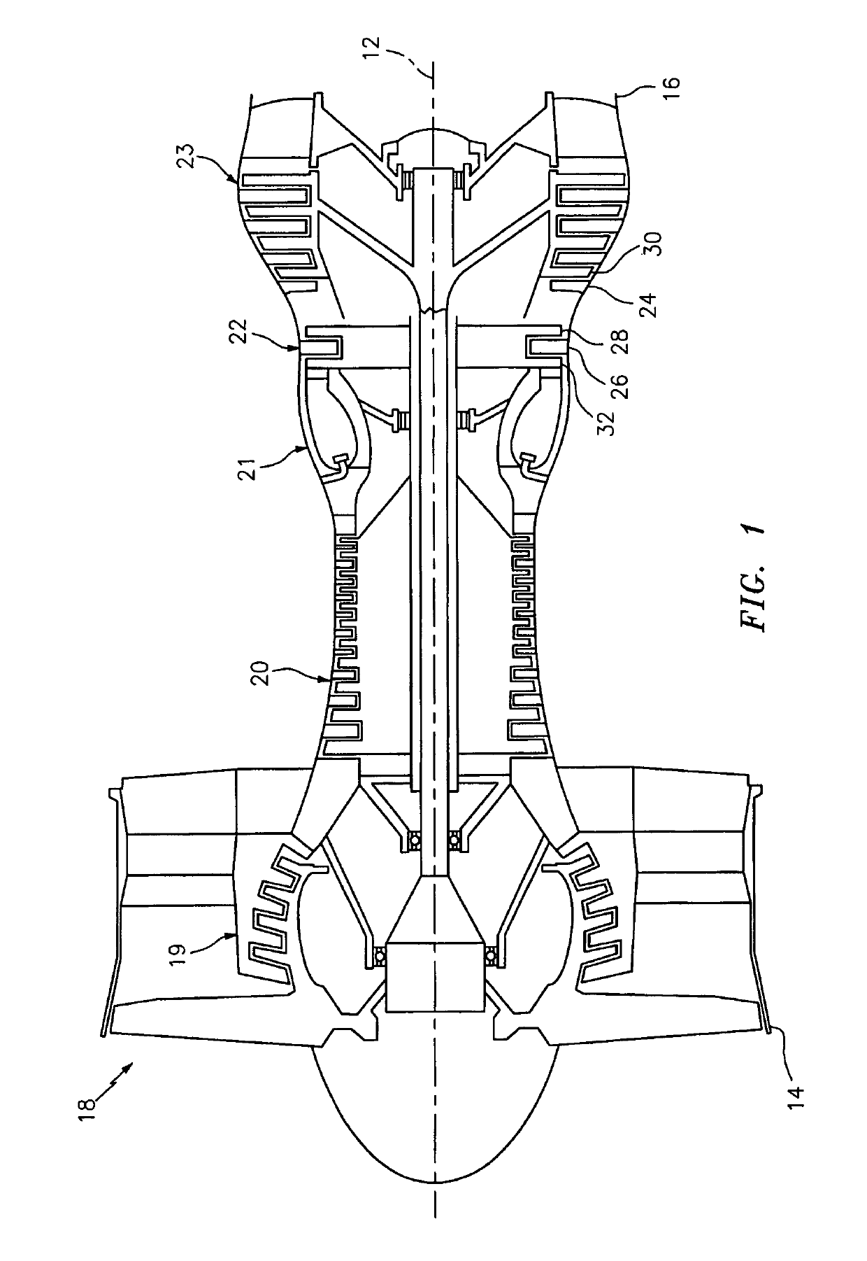
[0031]FIG. 1 illustrates a turbine engine 10 that extends along an axial centerline 12 between an upstream, airflow inlet 14 and a downstream, airflow exhaust 16. The turbine engine 10 includes a plurality of turbine engine sections such as, for example, a fan section 18, one or more (e.g., low and high pressure) compressor sections 19 and 20, a combustor section 21, and one or more (e.g., high and low pressure) turbine sections 22 and 23, which are sequentially arranged along the axial centerline 12. The turbine engine 10 also includes one or more stator vane arrangements (e.g., 24 and 26).

[0032]At least one of the stator vane arrangements may be configured to guide fluid between two of the turbine engine sections 18-23. The stator vane arrangement 24, for example, is configured to guide core gas from a rotor stage 28 of the turbine section 22 to an axially adjacent rotor stage 30 of the turbine section 23. At least one of the stator vane arrangements may also or alternatively be c...


PUM

PropertyMeasurementUnit
widthaaaaaaaaaa
widthsaaaaaaaaaa
temperatureaaaaaaaaaa

Abstract

A turbine engine vane arrangement and a method for manufacturing a turbine engine vane arrangement are provided. The vane arrangement includes a plurality of vane arrangement segments arranged circumferentially around an axial centerline. Each of the vane arrangement segments includes an airfoil that extends radially between a first platform segment and a second platform segment. The first platform segment extends circumferentially between a first mate face and a second mate face. The first mate face of a first of the vane arrangement segments is bonded to the second mate face of a second of the vane arrangement segments.

Description

[0001]This application claims priority to PCT Application N. PCT / US13 / 20832 filed Jan. 9, 2013, which claims priority to U.S. Provisional Appln. No. 61 / 707,505 filed Sep. 28, 2012, which is hereby incorporated by reference.BACKGROUND OF THE INVENTION[0002]1. Technical Field[0003]This disclosure relates generally to a turbine engine and, more particularly, to a stator vane arrangement that includes a plurality of vane arrangement segments.[0004]2. Background Information[0005]A typical turbine engine includes a plurality of engine sections such as, for example, a fan section, a compressor section, a combustor section and a turbine section. The turbine engine may also include a stator vane arrangement. The vane arrangement may be configured to guide core gas between adjacent rotor stages within a respective one of the engine sections. Alternatively, the vane arrangement may be configured to guide core gas between an adjacent pair of the engine sections.[0006]A typical stator vane arran...

Claims


Application Information

Patent Timeline
Patent Type & Authority Patents(United States)
IPC IPC(8): F01D9/04B23P15/04F04D29/54
CPCF01D9/042F04D29/544F01D9/044B23P15/04
Inventor FARAH, JORGE I.BURT, JONATHAN P.STEWART, DANA P.
Owner RTX CORP
Features
  • R&D
  • Intellectual Property
  • Life Sciences
  • Materials
  • Tech Scout
  • Unparalleled Data Quality
  • Higher Quality Content
  • 60% Fewer Hallucinations
Learn More