
Illumination device

a technology of a light guide plate and a slit, which is applied in the direction of fixed installation, lighting and heating apparatus, instruments, etc., can solve the problems of difficult control of the distribution of light emitted from opacity and interference between the dots on the front surface and the dots on the rear surface, etc., to reduce interference, suppress the generation of moire, and improve the appearance of the light guide plate

Inactive Publication Date: 2019-03-26
PANASONIC INTELLECTUAL PROPERTY MANAGEMENT CO LTD
View PDF8 Cites 1 Cited by
  • Summary
  • Abstract
  • Description
  • Claims
  • Application Information

AI Technical Summary

Benefits of technology

[0006]In view of the above, the present disclosure provides an illumination device provided with a light guide plate having a front surface and a rear surface on which dots are formed, the illumination device being capable of improving the appearance thereof, controlling light distribution with the light guide plate and suppressing generation of a moire.
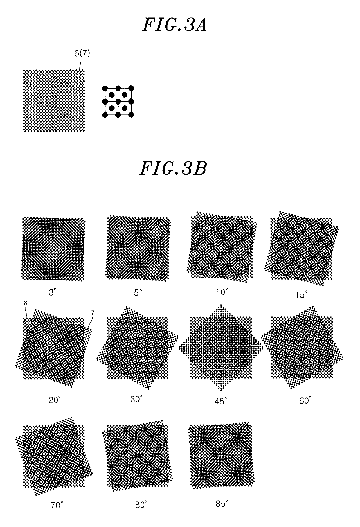
[0008]According to the illumination device described above, it is possible to reduce the interference between the dots of one emission surface (front surface) and the dots of the other emission surface (rear surface) without adding a light diffusion property to the light guide plate. Thus, it is possible to make the light guide plate transparent, thereby improving the appearance of the light guide plate.
[0009]Furthermore, it is possible to control the light distribution with the light guide plate and to suppress generation of a moire.

Problems solved by technology

However, in the aforementioned illumination device, the dots on the front surface and the dots on the rear surface interfere with each other.
However, the addition of the light diffusion property makes it difficult to control the distribution of the light emitted from the light guide plate.
Particularly, when the illumination device is turned off, the opacity of the light guide plate is noticeable and the appearance of the light guide plate is poor.

Method used


Image

  • Illumination device
  • Illumination device
  • Illumination device

Examples


Embodiment Construction

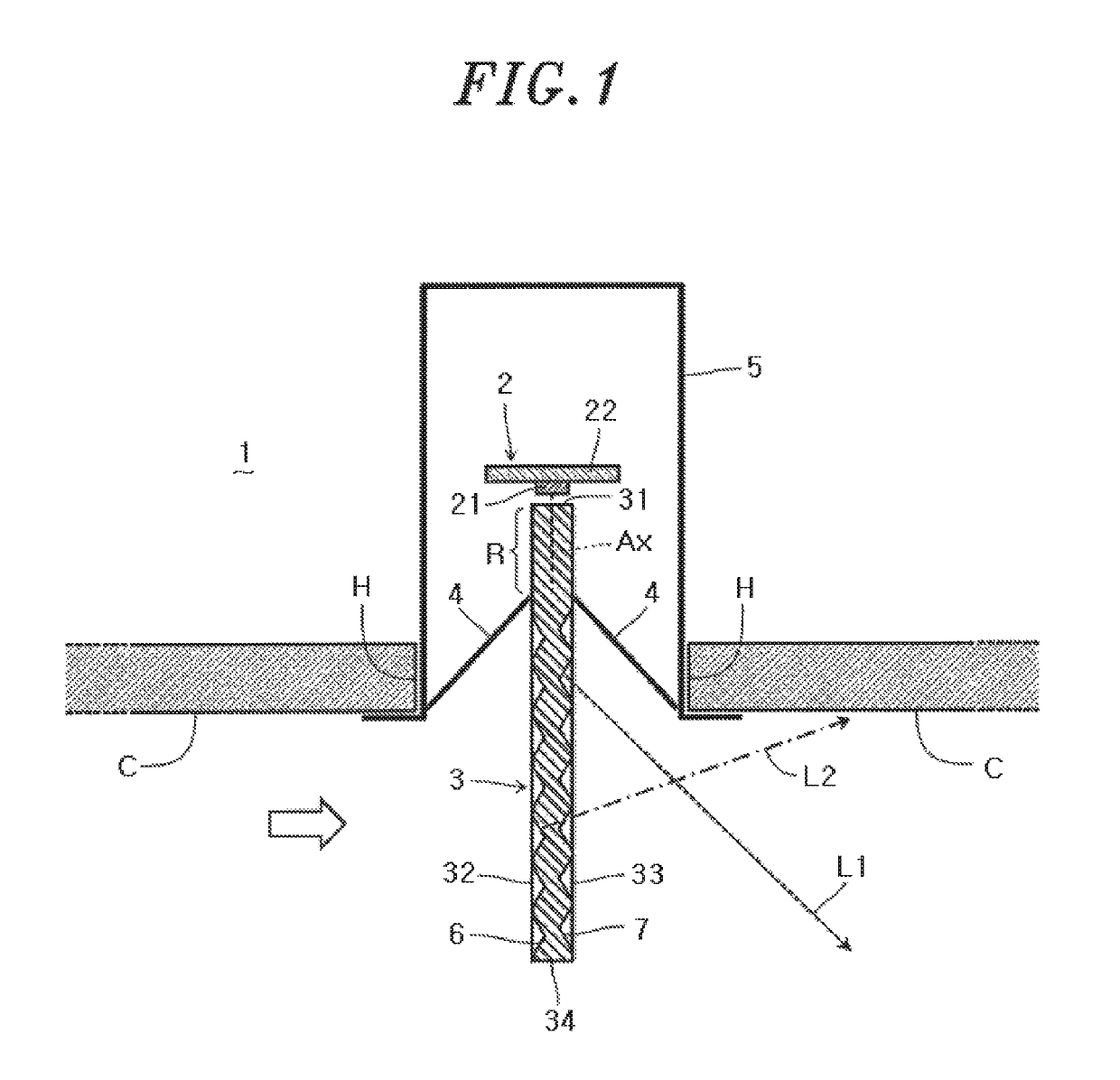
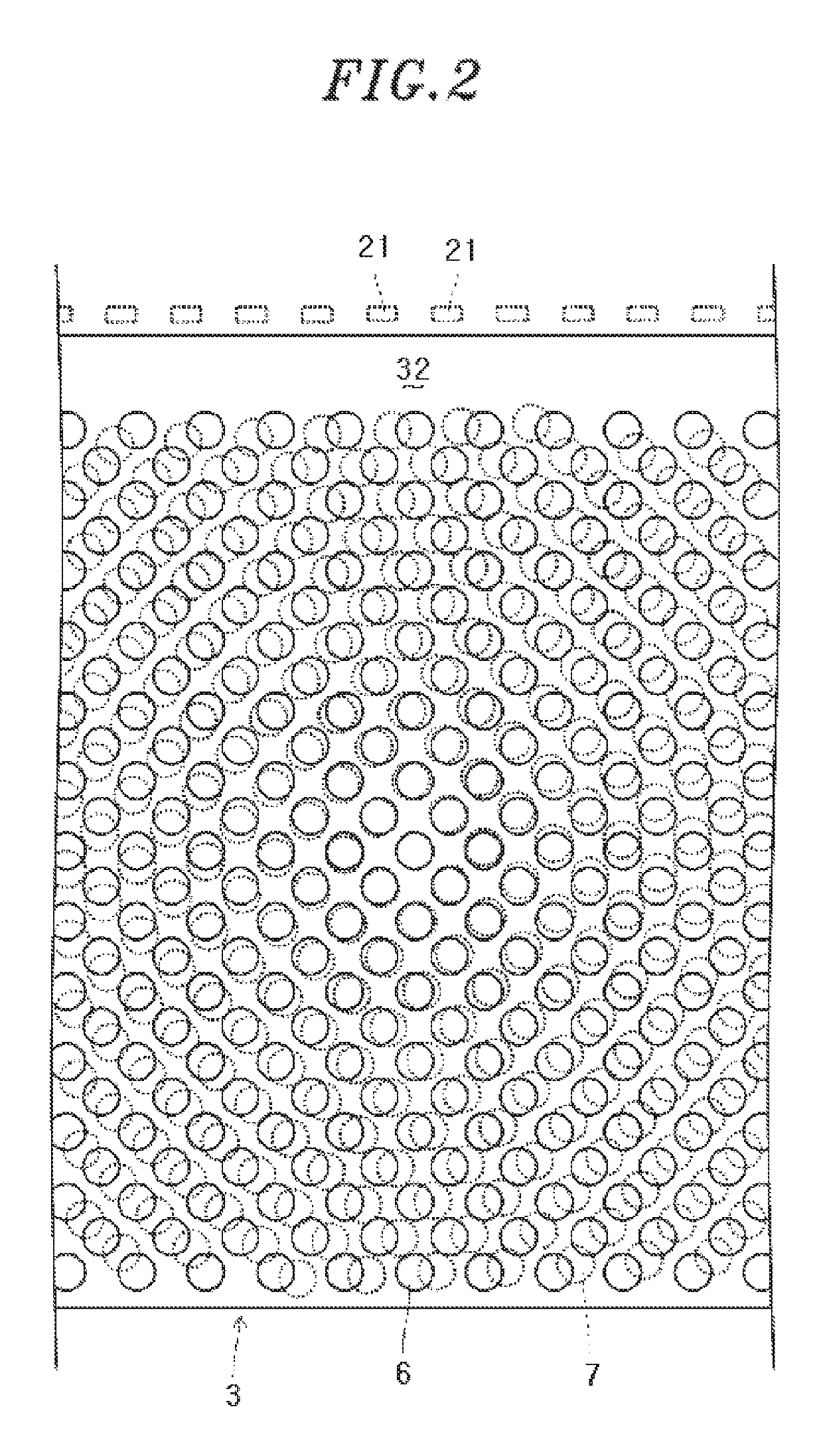
[0021]An illumination device according to one embodiment will be described with reference to FIGS. 1 to 9B. As illustrated in FIG. 1, the illumination device 1 is embedded in a ceiling C. The illumination device 1 includes an light source unit 2, a light guide plate 3 configured to guide light from the light source unit 2 and to emit the light outward, a reflection plate 4 configured to reflect the light from the light guide plate 3 toward a floor surface (downward), and a case 5 configured to hold the light source unit 2, the light guide plate 3 and the reflection plate 4. The case 5 is formed of a frame embedded in a hole H provided in the ceiling C and is configured to hold the light source unit 2, the light guide plate 3 and the reflection plate 4 in a specified position using a holding structure (not shown).

[0022]The light source unit 2 includes LEDs 21 and a wiring board 22 on which the LEDs 21 are mounted. The LEDs 21 are provided in a plural number and are disposed in rows a...


PUM


Abstract

An illumination device includes a light source unit; and a light guide plate configured to guide light from the light source unit and to emit the light outward. The light guide plate includes an incidence surface which constitutes one end surface of the light guide plate and on which the light from the light source unit is incident, and emission surfaces which constitute opposite main surfaces of the light guide plate and from which the light incident on the incidence surface is emitted. The emission surfaces include dots formed by micro prism processing. The dots on one of the emission surfaces and the dots on the other emission surface are position-shifted in rotational symmetry with each other.

Description

CROSS-REFERENCE TO RELATED APPLICATIONS[0001]This application claims priority to Japanese Patent Application No. 2015-127919, filed Jun. 25, 2015, the entire contents of which are hereby incorporated by reference.TECHNICAL FIELD[0002]The present disclosure relates to an illumination device provided with a light guide plate.BACKGROUND ART[0003]Conventionally, there is known an illumination device provided with a light guide plate which guides light emitted from a light source unit and emits the light outward (see, e.g., Japanese Unexamined Patent Application Publication No. 2011-3367). The light guide plate includes, for example, fine concave pattern marks (dots) disposed in a matrix shape on the opposite main surfaces (a front surface and a rear surface) thereof. The light is emitted outward through the dots. The dots are arranged in, for example, a square lattice pattern. The dots on the front surface are offset with respect to the dots on the rear surface in the arrangement direct...

Claims


Application Information

Patent Timeline
Patent Type & Authority Patents(United States)
IPC IPC(8): F21S8/02F21V8/00F21Y101/00
CPCF21S8/026G02B6/0036G02B6/0076G02B6/0065G02B6/009G02B6/0055F21Y2101/00
Inventor SAIMI, MOTOHIROTANAHASHI, OSAMU
Owner PANASONIC INTELLECTUAL PROPERTY MANAGEMENT CO LTD
Learn More