
Supporting device for a furniture flap

Active Publication Date: 2019-04-02
JULIUS BLUM GMBH
View PDF32 Cites 4 Cited by
  • Summary
  • Abstract
  • Description
  • Claims
  • Application Information

AI Technical Summary

Benefits of technology

The present invention is a support device for a furniture flap that improves upon existing designs. It is easy to produce and operates with high reliability and safety.

Problems solved by technology

A disadvantage with that state of the art is the complicated and expensive structure of the parallel kinematic arrangement and the formation of a shearing gap, caused by the arrangement of the lever arms, and the risk of injury linked thereto when the furniture door is operated by a user.

Method used


Image

  • Supporting device for a furniture flap
  • Supporting device for a furniture flap
  • Supporting device for a furniture flap

Examples


Embodiment Construction

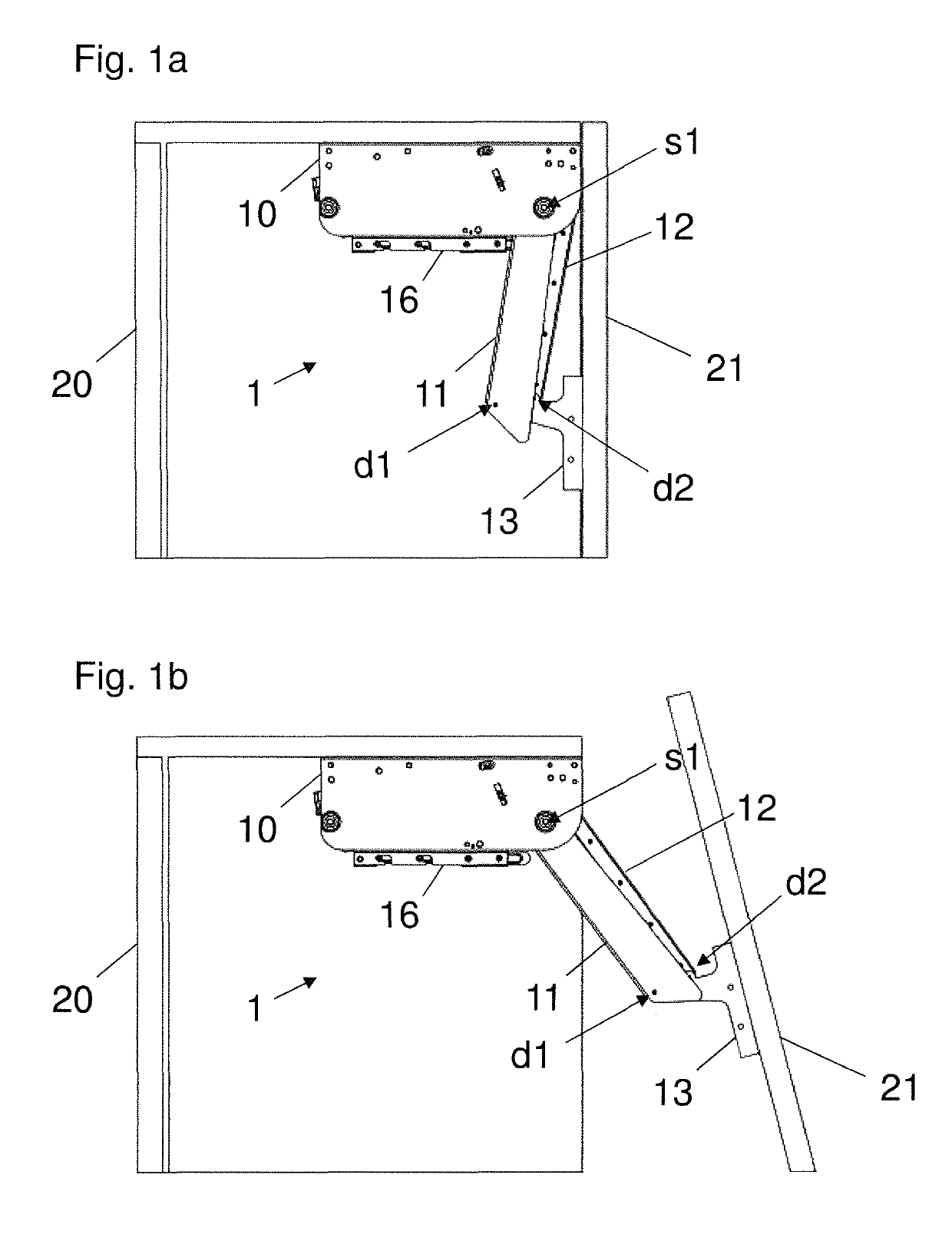
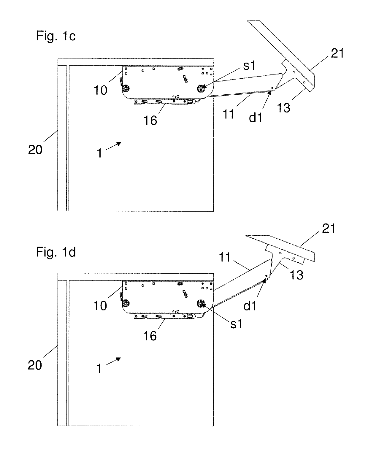
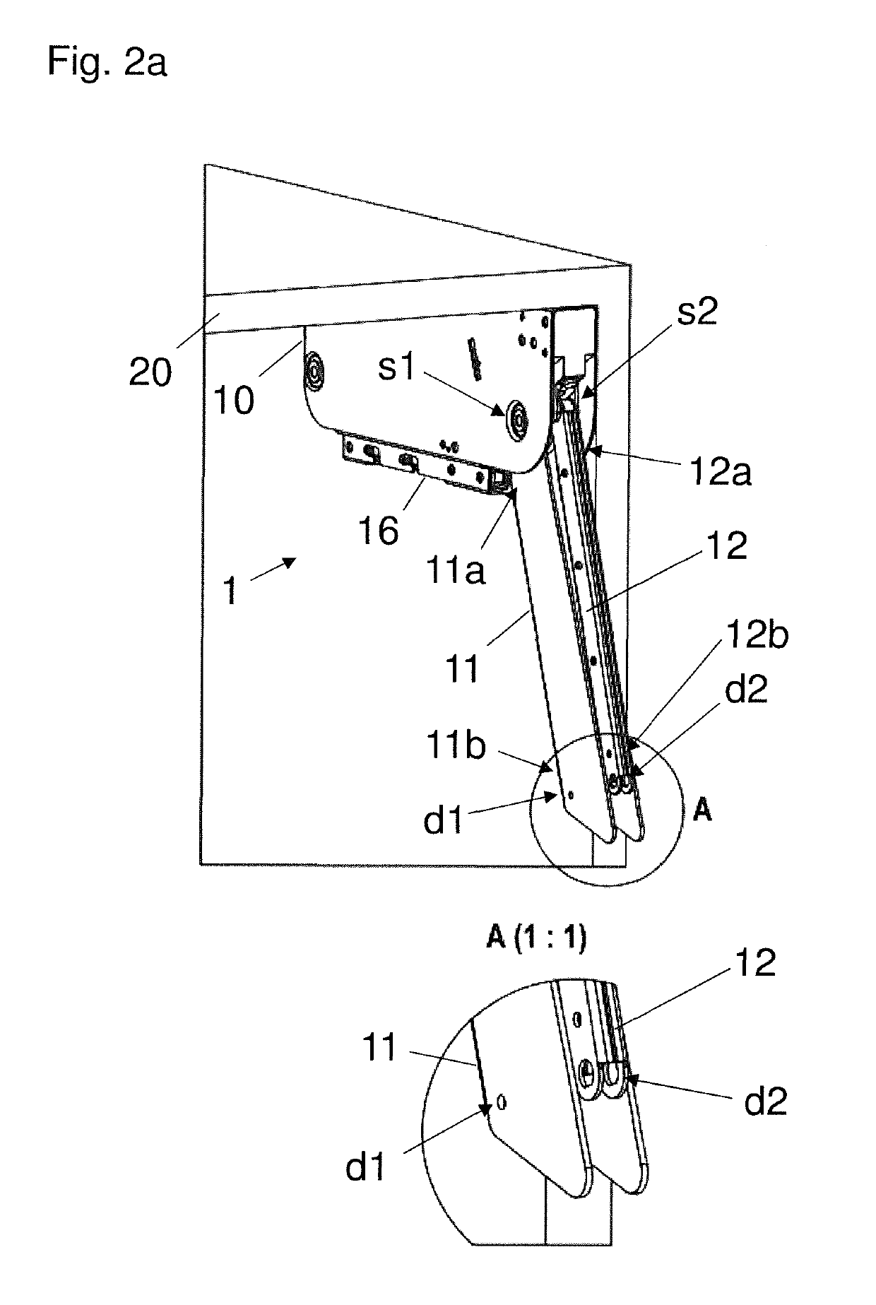
[0028]FIG. 1a shows a support device 1 in a position corresponding to a closed position of a furniture flap 21. In this arrangement, the support device 1 has a housing 10 which can be mounted to a furniture carcass 20 and having a first support arm 11 mounted pivotably about a first pivot axis s1, and a second support arm 12 mounted pivotably about a second pivot axis s2 (not visible here). In this case, the first support arm 11 is further connected to a hinged connection 13 which is mounted rotatably about a first axis of rotation d1 and which is also connected to the second support arm 12 rotatably about a second axis of rotation d2. The movement of the first and second support arms 11, 12 is thus coupled by the hinged connection 13. In this position of the support device 1 (corresponding to the closed position), the second support arm 12 is arranged partially in the cavity afforded by the profile of the first support arm 11 substantially over the entire length of the second suppo...


PUM


Abstract

A supporting device for a furniture flap can be connected to a furniture body and a furniture flap in an articulated manner. The supporting device has a first supporting arm and a second supporting arm, and the first and the second supporting arms overlap without a gap laterally with respect to the direction of motion of the supporting device in each position of the supporting device. The first supporting arm and the second supporting arm are profiled in the cross-section and are nested in each other.

Description

BACKGROUND OF THE INVENTION[0001]The present invention concerns a support device for a furniture flap, and an article of furniture having at least one such support device.[0002]Support devices for furniture flaps are known in many different configurations in the state of the art. U.S. Pat. No. 8,904,600 B2 describes, for example, a hinge device for an article of furniture having a furniture door which has fixing means at the carcass side, two or three lever arms hingedly fixed thereto, and door-side fixing means which are also hingedly fixed to the lever arms. The aim of that hinge device is to guide an opening or closing movement of a furniture door, in which case the furniture door is not rotated about a perpendicular axis of rotation but rather is displaced parallel in a horizontal plane. That is achieved by a parallel kinematic arrangement comprising two or three levers of equal length, which at the body side and the door side are rotatably mounted at respectively equal spacings...

Claims


Application Information

Patent Timeline
IPC IPC(8): E05D3/14E05D15/32E06B3/44
CPCE05D3/142E05D3/14E06B3/443E05D15/32E05Y2900/212E05Y2900/20E05D15/463
Inventor BRUNNMAYR, HARALD
Owner JULIUS BLUM GMBH
Learn More