
Filling machine

Active Publication Date: 2015-08-27
KHS GMBH
View PDF0 Cites 4 Cited by
  • Summary
  • Abstract
  • Description
  • Claims
  • Application Information

AI Technical Summary

Benefits of technology

The invention is a filling machine that has a simple design and is very reliable and efficient. It has also been designed to promote good cleaning practices for the machine and its components.

Problems solved by technology

This known filling machine is structurally costly.
Additionally, it is not suitable for aseptic filling of containers.
This filling machine is structurally costly because of the devices for cleaning the dispensing nozzles.
This makes it unsuitable for aseptic filling.
A disadvantage of this type of cleaning system is that the resulting dense population of rinsing caps restricts structural freedom and imposes undesirable design constraints.
A disadvantage of this kind of filling machine is that both the filling elements and the isolator chamber must be cleaned.
Another problem that arises in this kind of filling machine is that the drives for moving the rinsing caps between their starting position and working position are arranged inside the isolator chamber.

Method used


Image

  • Filling machine
  • Filling machine
  • Filling machine

Examples


Embodiment Construction

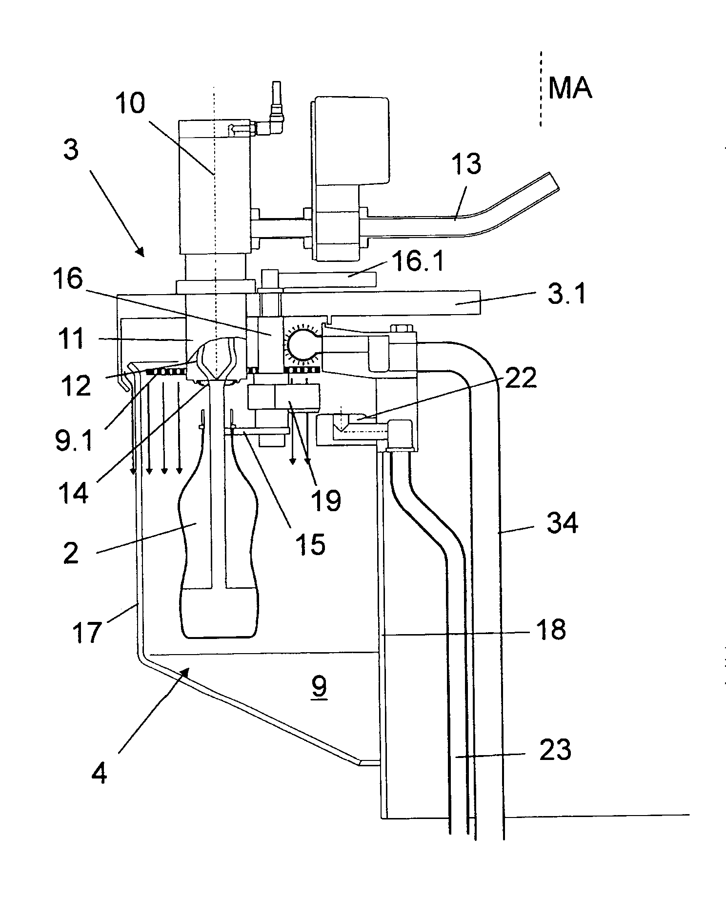
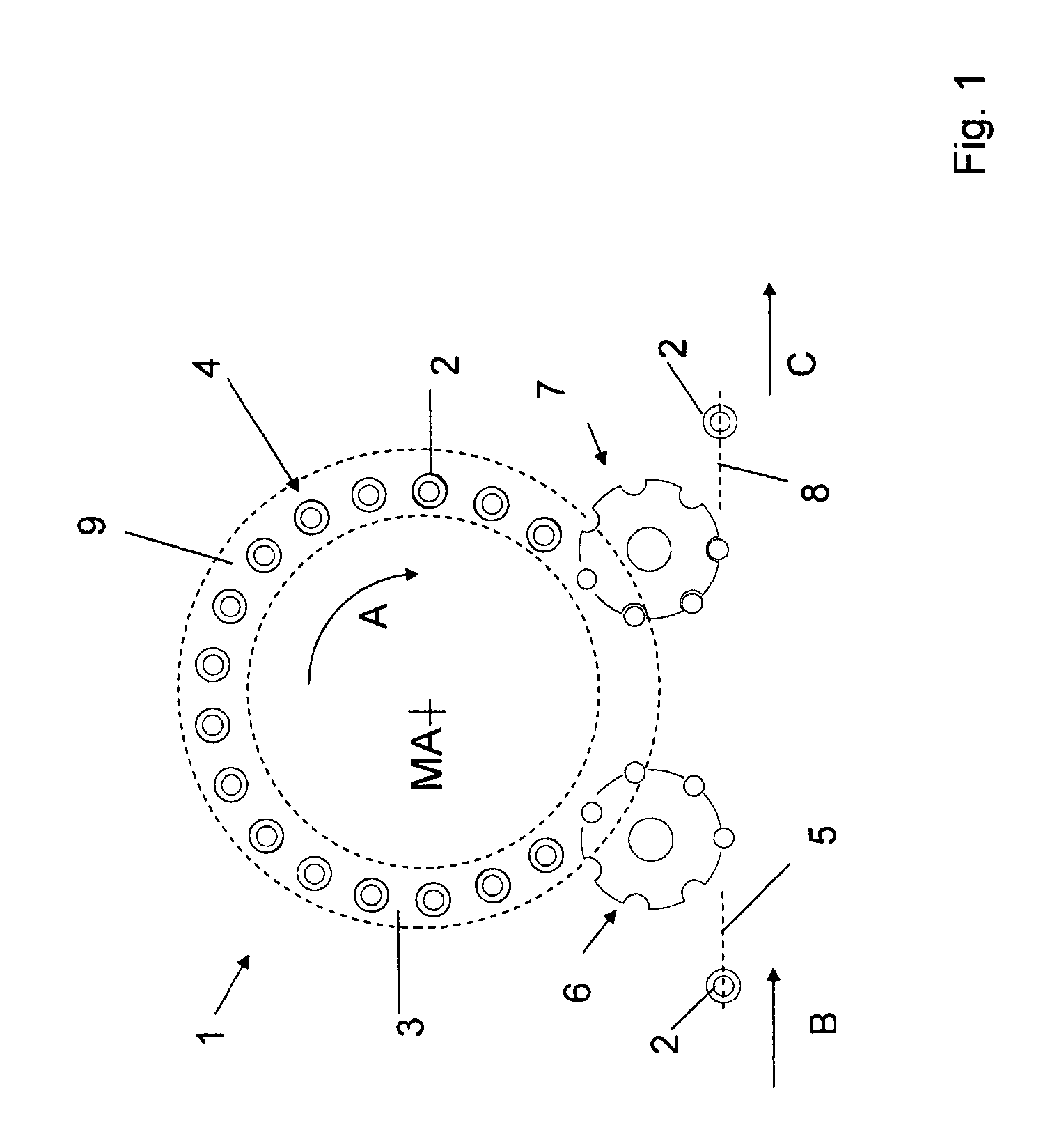
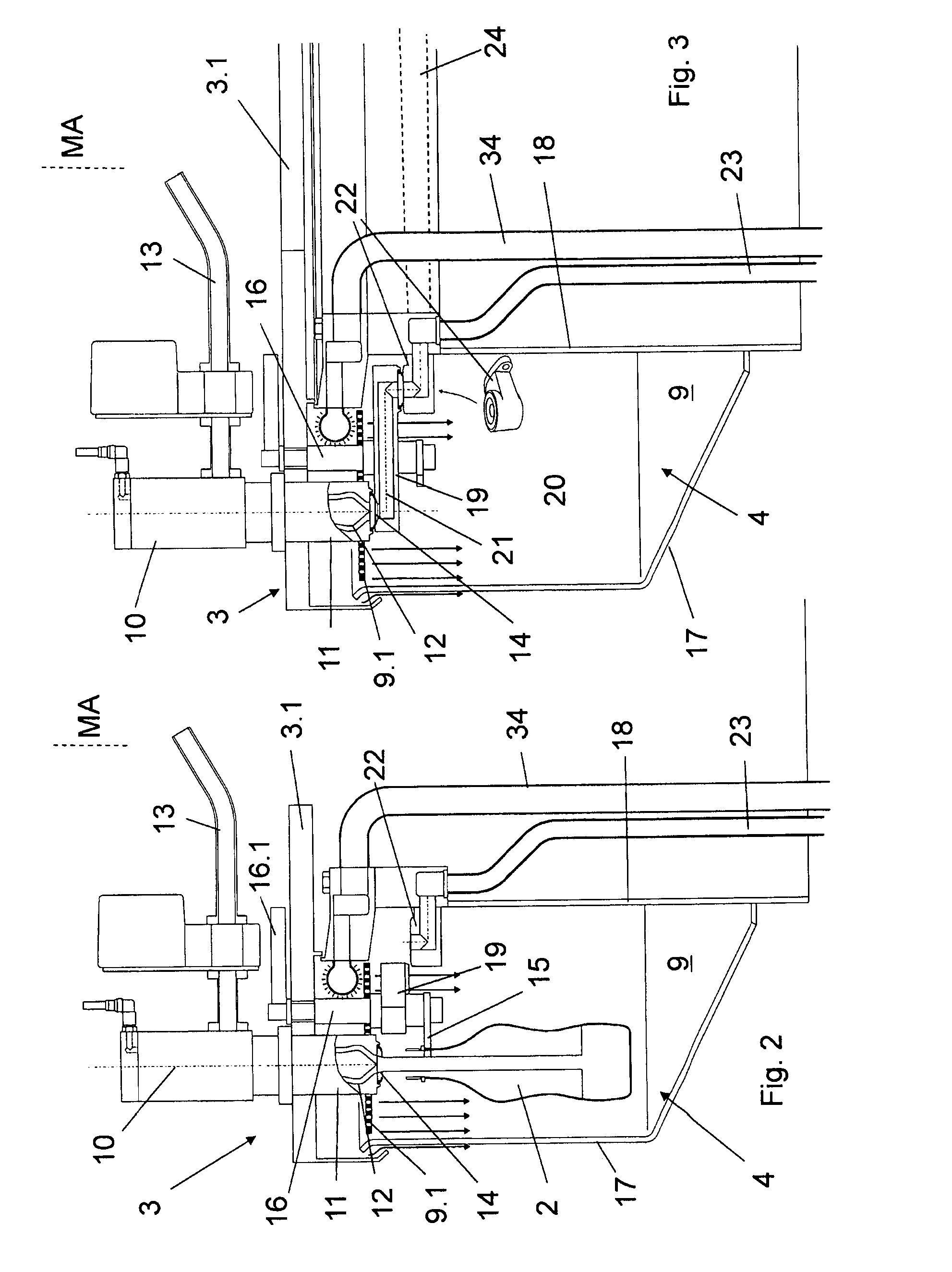
[0043]Referring to FIG. 1, a rotating filling machine 1 for aseptic free-jet filling of containers 2, and in particular, bottles, with a liquid filling material has a rotor 3 that can rotate in a rotation direction A about a vertical machine axis MA so that it functions as a transport element. A plurality of filling positions 4 is formed on the circumference of this rotor 3. These filling positions 4 are distributed at regular angular distances around the machine axis MA and at the same radial distance from the machine axis MA. In other words, if a polar coordinate system is defined with the machine axis MA at the origin, the filling positions 4 are located at (r, nΔθ) where n=0, 1, 2 . . .

[0044]An external conveyor 5 transports empty containers 2 along an inflow direction B towards a container inlet 6, where they are transferred to respective filling positions 4. At a container outlet 7, an external conveyor 8 removes filled containers 2 from the filling positions 4 and transports ...


PUM

PropertyMeasurementUnit
Flow rateaaaaaaaaaa
Areaaaaaaaaaaa

Abstract

A container-filling machine includes a rotor, a machine rack that doesn't move with the rotor, filling positions formed on the rotor, rinsing-cap elements used during CIP cleaning, each associated with a filling position, and a housing that isolates filling positions during aseptic filling. Each rinsing-cap element includes a rinsing cap at one end and a connection at the other. An outflow channel extends between the ends. The rinsing-cap element moves from a first position, in which it is outside a space occupied by a container being filling, and a second position, in which it lies sealed against a filling element. In the second position, the rinsing-cap element and the outflow channel connect to a fixed discharge on the machine rack. Each rinsing cap element moves between the first and second position by swiveling a swiveling element about an axis thereof between the two positions.

Description

RELATED APPLICATIONS[0001]This application is the U.S. National Stage under 35 USC 371 of international application PCT / EP2013 / 002889, filed on Sep. 26, 2013, which claims the benefit of the Sep. 28, 2012 priority date of German application DE 10 2012 019 161.8, the contents of which are herein incorporated by reference.FIELD OF INVENTION[0002]The invention relates to filling machines, and in particular, to filling machines for aseptic free-jet filling of containers.BACKGROUND[0003]Known filling machines for filling bottles or similar containers with a liquid filling material typically include a rotor having a plurality of filling positions, each having one filling element. The filling positions are disposed on the rotor so that they rotate with the rotor about a vertical machine axis.[0004]Filling machines of this type require periodic cleaning. To achieve this, a cleaning assembly is provided on the machine rack of the filling machine. This machine rack does not rotate with the ro...

Claims


Application Information

Patent Timeline
IPC IPC(8): B67C3/00B67C3/22B67C3/02
CPCB67C3/004B67C2003/228B67C3/225B67C3/02B67C2003/2694
Inventor CLUSSERATH, LUDWIGBRUCH, BERND
Owner KHS GMBH
Learn More