Detachable blades for a ceiling fan

a ceiling fan and detachable technology, applied in the direction of non-positive displacement fluid engines, pump components, liquid fuel engine components, etc., can solve the problems of unstable hanging rods and outer shields, user danger, and difficulty in replacing blades while on the job

Active Publication Date: 2019-04-16
AIR COOL INDAL
View PDF4 Cites 0 Cited by
  • Summary
  • Abstract
  • Description
  • Claims
  • Application Information

AI Technical Summary

Benefits of technology

[0006]Still another object of the detachable blades for a ceiling fan according to the present invention is to provide a spherical cover to be used for the amounting of the plurality of blades of the ceiling fan so that the surface of the blades can be flat but to rotate not horizontal with respect to the ground causing a sufficient air flow for the user.
[0008]Another feature of the detachable blades for a ceiling fan according to the present invention is to provide a blade comprising a guiding slot to match with a guide on the cover plate so that the blade can be easily and accurately inserted to the blade seat.

Problems solved by technology

It is noted that the hanging rod and the outer shield may become unstable and even damaged due to the material made of the same also the continuous use of rotation driven by the motor.
The blades may even fall down causing danger to the user.
Another disadvantage of a conventional ceiling fan is the difficulty in the replacement of the blades while they are used after a period of time.
Although this conventional assembly of the blades of a ceiling fan can achieve the goal to quickly assemble the blades of the ceiling fan, it is noted that the blades shall not be detached easily after used for a period of time.
Also, the connecting arm 2 may not be strong enough to support a long time rotation of the blades.

Method used


Image

  • Detachable blades for a ceiling fan
  • Detachable blades for a ceiling fan
  • Detachable blades for a ceiling fan

Examples


Embodiment Construction

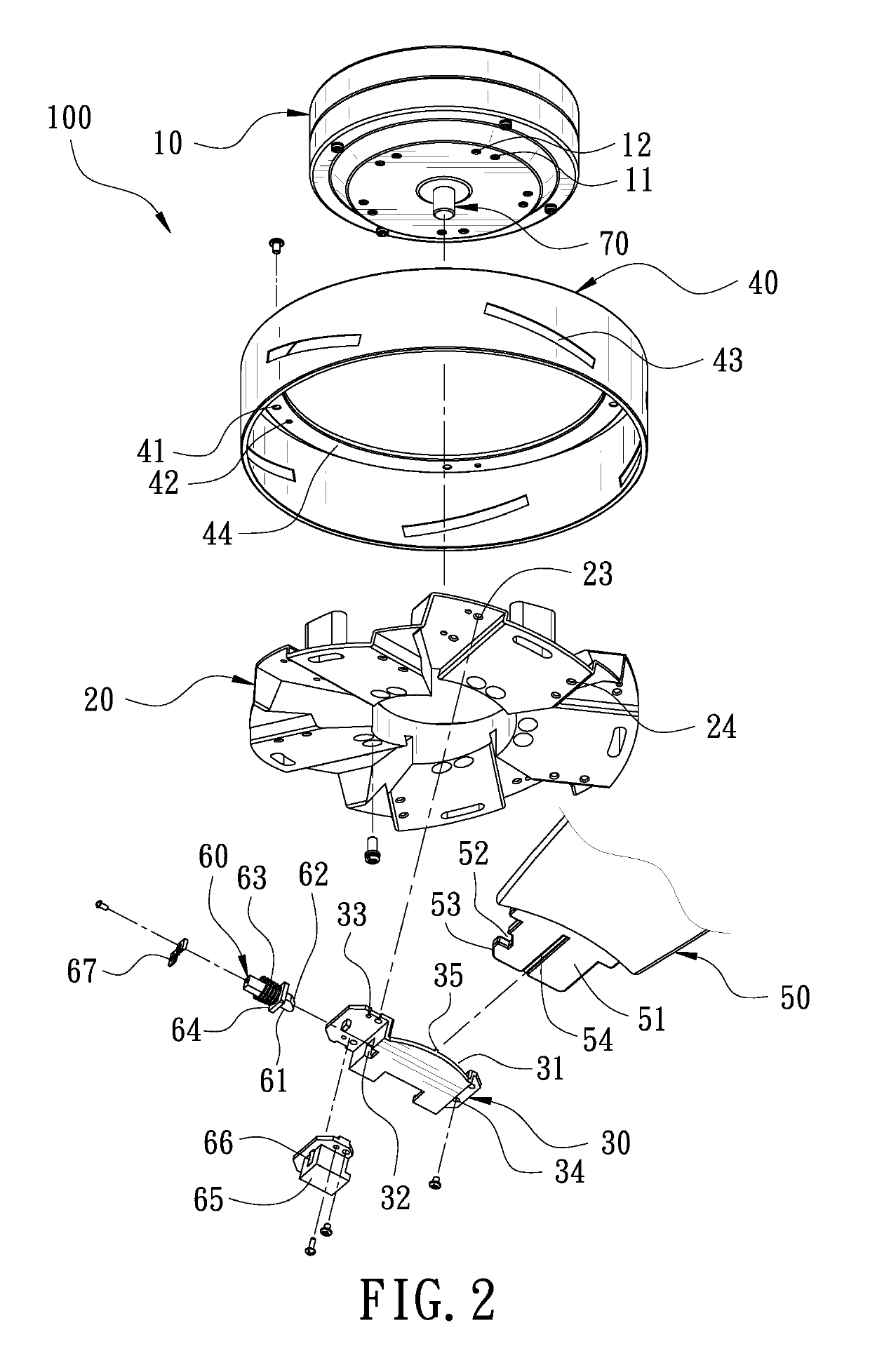
[0019]Referring to FIG. 2 which shows an exploded perspective view of an embodiment of a detachable blade for a ceiling fan according to the present invention, the entire ceiling fan structure 100 comprises a motor 10, a blade seat 20, a cover plate 30, a spherical cover 40 and a blade 50.

[0020]The motor 10 has a plurality of motor positional holes 11 and a plurality of motor screw holes 12. If an illumination lamp shall be provided below the ceiling fan 100, the lamp can be connected to the electric lamp base 70.

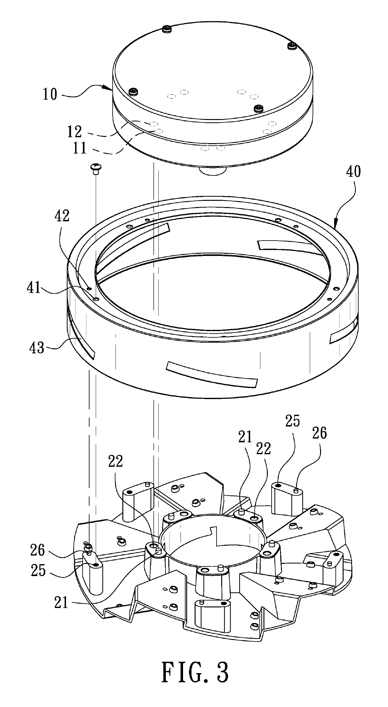
[0021]The blade seat 20 has a plurality of first seat lugs 21 and a plurality of first seat screw holes 22 in correspondence to the motor positioning holes 11 and the motor screw holes 12 on the motor 10.

[0022]Also with reference to FIG. 3 which shows an exploded view of the spherical cover and the blade seat of the embodiment of the detachable blade for a ceiling fan according to the present invention in a different view angle rather than the same shown in FIG. 2, the blad...


PUM


Abstract

A detachable blade structure has a blade seat, a motor, a cover plate, a spherical cover, a blade, a detachable member and first and second screws. The spherical cover has a cover slot, a cover positioning hole and a cover screw hole. The cover plate has a chamber. The blade is inserted through the cover slot and inserted into the chamber. The blade seat has a first seat lug, a first seat screw hole, a second seat lug and a second seat screw hole. The motor has a motor positioning hole and a motor screw hole. The first seat lug is inserted into the motor positioning hole. The first screw is screwed into the first seat screw hole and the motor screw hole. The second seat lug is inserted into the cover positioning hole. The second screw is screwed into the second seat screw hole and the cover screw hole.

Description

BACKGROUND OF THE INVENTION[0001]The present invention relates to a structure of detachable blades for a ceiling fan.[0002]A conventional ceiling fan, in its structure, comprises a motor covered by a outer shield and a frame for the installation of a plurality of blades to be rotated by the motor. At the outer shield, there is hanging rod for the entire ceiling fan to be assembled under the ceiling of a house. It is noted that the hanging rod and the outer shield may become unstable and even damaged due to the material made of the same also the continuous use of rotation driven by the motor. The blades may even fall down causing danger to the user.[0003]Another disadvantage of a conventional ceiling fan is the difficulty in the replacement of the blades while they are used after a period of time. There was an invention for a quick assembly of blades of a ceiling fan disclosed in U.S. Pat. No. 6,171,059B1. FIG. 1 shows the blades assembly of the conventional ceiling fan according to ...

Claims


Application Information

Patent Timeline
Patent Type & Authority Patents(United States)
IPC IPC(8): F04D29/34F04D25/08
CPCF04D25/088F04D29/34
Inventor WANG, CLIFF
Owner AIR COOL INDAL
Why Eureka
Try Eureka