Hose system

a hose system and hose technology, applied in the direction of machines/engines, flexible member pumps, positive displacement liquid engines, etc., can solve the problems of complex and cost-intensive mechanical adjustment, disadvantageous system use, and adapted pump hoses

Active Publication Date: 2019-04-23
SARTORIUS STEDIM BIOTECH GMBH
View PDF7 Cites 1 Cited by
  • Summary
  • Abstract
  • Description
  • Claims
  • Application Information

AI Technical Summary

Benefits of technology

[0010]A second stop element may be provided so that a distance from the first stop element can be adjusted by moving at least the first stop element. The second stop element may be pre-installed on the pump hose in a fixed position. However, the first stop element can be moved to adapt the distance between the two stop elements to the particular pump head. Alternatively, the second stop element can be pre-installed movably and can be brought to a fixed position. Thus, both stop elements can be moved on the pump hose and brought to predefinable positions so that the distance between the two stop elements can be adapted to the pump head.
[0012]The pre-installation of the movable stop elements advantageously enables the pump hoses to be incorporated in a complete system that may comprise the entire pump hose and stop elements do not have to be plugged on from the side.
[0017]The pump hose may have has a surface area that is suitable for a hook-and-loop fastener and on which a hook-and-loop tape forming an abutment for the movable stop element can be secured. However, the hook-and-loop tape can also be secured both on the pump hose and also on a shoulder of the stop element and can fix the stop element in both directions.

Problems solved by technology

These systems disadvantageously can be used only with specific pump hoses and their stop elements are adapted to a defined pump.
However, the mechanical adjustment is complicated and cost-intensive.
This case also disadvantageously requires pump hoses adapted to the pump.

Method used


Image

  • Hose system
  • Hose system
  • Hose system

Examples


Embodiment Construction

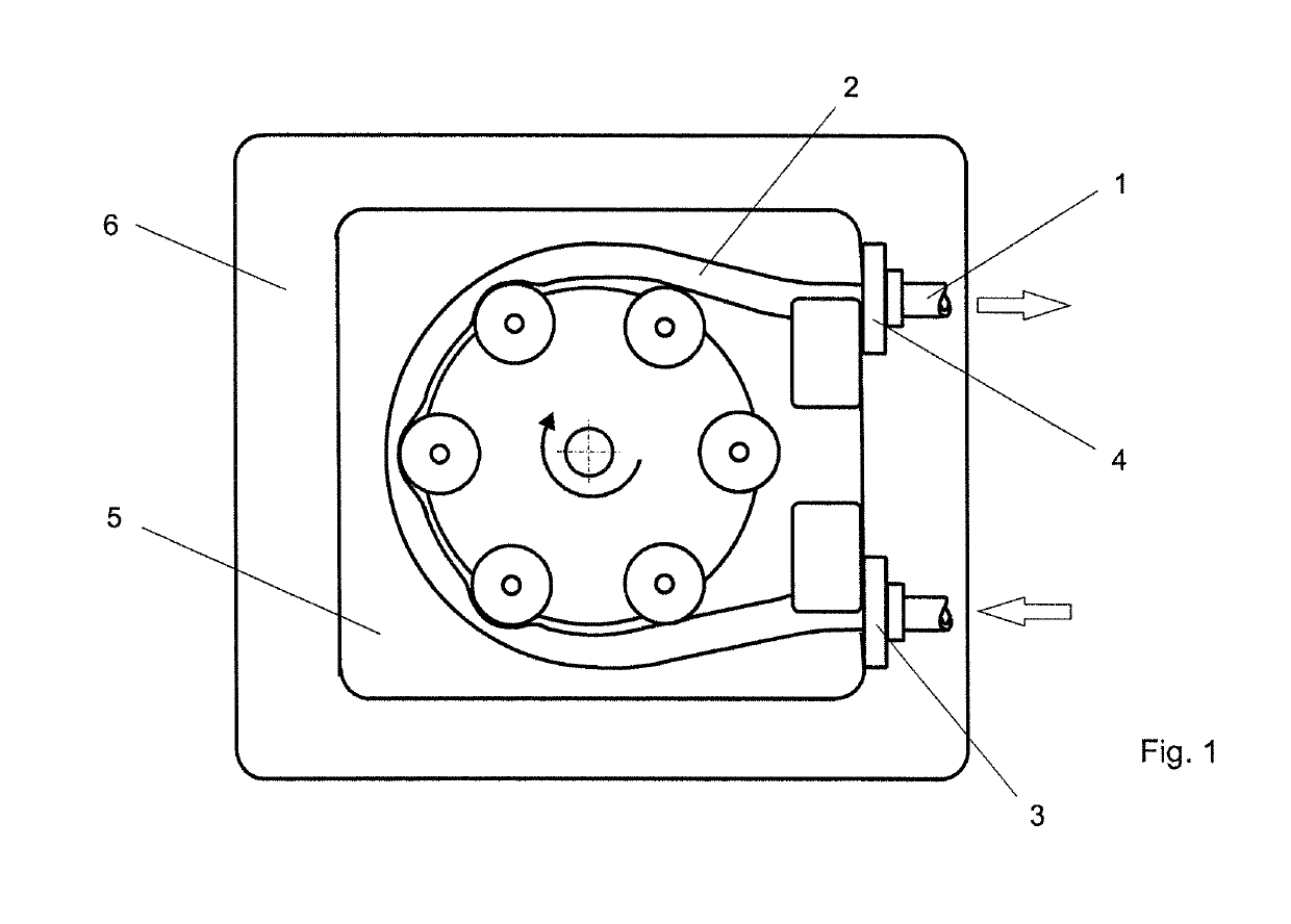
[0027]A hose system is composed principally of a pump hose 1 with a hose portion 2, a first stop element 3 and a second stop element 4.

[0028]The pump hose 1 can be inserted with its hose portion 2 into a pump head 5 of a hose pump 6.

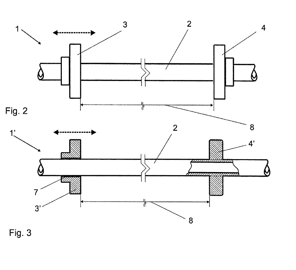
[0029]The first stop element 3 is arranged movably on the hose portion 2 and can be connected immovably to the pump hose 1 at a predefinable position. According to the embodiment in FIG. 2, the second stop element 4 also is arranged longitudinally movably on the pump hose 1 and can be fixed immovably on the pump hose 1 like the first stop element 3.

[0030]According to the embodiment in FIG. 3, the first stop element 3′ has an adhesive layer 7 that can be activated by an external influence, and the first stop element 3′ is fixed immovably on the pump hose 1. According to the illustrative embodiment in FIG. 3, the second stop element 4′ is applied to the pump hose by encapsulation in an overmolding or insert molding process and thus pre-installed in a fixed...


PUM


Abstract

A hose system has a pump hose with a hose portion insertable into a pump head of a hose pump. The hose portion has at least a first stop element fixing the hose portion in the feed direction. The first stop element can subsequently be connected immovably to the pump hose at a predefinable position of the pump hose. Thus, the pump hose can be used more universally and can be adapted to different pump heads.

Description

BACKGROUND OF THE INVENTION[0001]1. Field of the Invention[0002]The invention relates to a hose system with a pump hose which has a hose portion insertable into a pump head of a hose pump and which has at least a first stop element fixing the hose portion in the feed direction.[0003]2. Description of the Related Art[0004]Hose pumps with a peristaltic feed action often are used in biotechnology, pharmacy and medicine, particularly in connection with disposable products.[0005]U.S. Pat. No. 5,388,972 A and EP 1 400 691 B1 use a roller pump and employ stop elements on the input and output sides to avoid a “migration” of the pump hose. Each stop element is fit in corresponding recesses of the pump head. These systems disadvantageously can be used only with specific pump hoses and their stop elements are adapted to a defined pump.[0006]U.S. Pat. No. 5,318,413 A discloses a peristaltic pump in the pump hose of which the recess for one of two stoppers is mechanically adjustable. Different h...

Claims


Application Information

Patent Timeline
Patent Type & Authority Patents(United States)
IPC IPC(8): F04B43/12
CPCF04B43/1261
Inventor REIF, OSCAR-WERNERPRIEBE, PAUL
Owner SARTORIUS STEDIM BIOTECH GMBH
Why Eureka
Try Eureka