Integrated contactor mounting post

a technology of contactor mounting post and contactor, which is applied in the direction of relays, contact heating/cooling, transportation and packaging, etc., can solve the problem of inefficient cooling methods

Active Publication Date: 2019-04-23
HAMILTON SUNDSTRAND CORP
View PDF31 Cites 7 Cited by
  • Summary
  • Abstract
  • Description
  • Claims
  • Application Information

AI Technical Summary

Problems solved by technology

Such cooling methods tend to be inefficient, however, for certain high power applications.

Method used


Image

  • Integrated contactor mounting post
  • Integrated contactor mounting post
  • Integrated contactor mounting post

Examples


Embodiment Construction

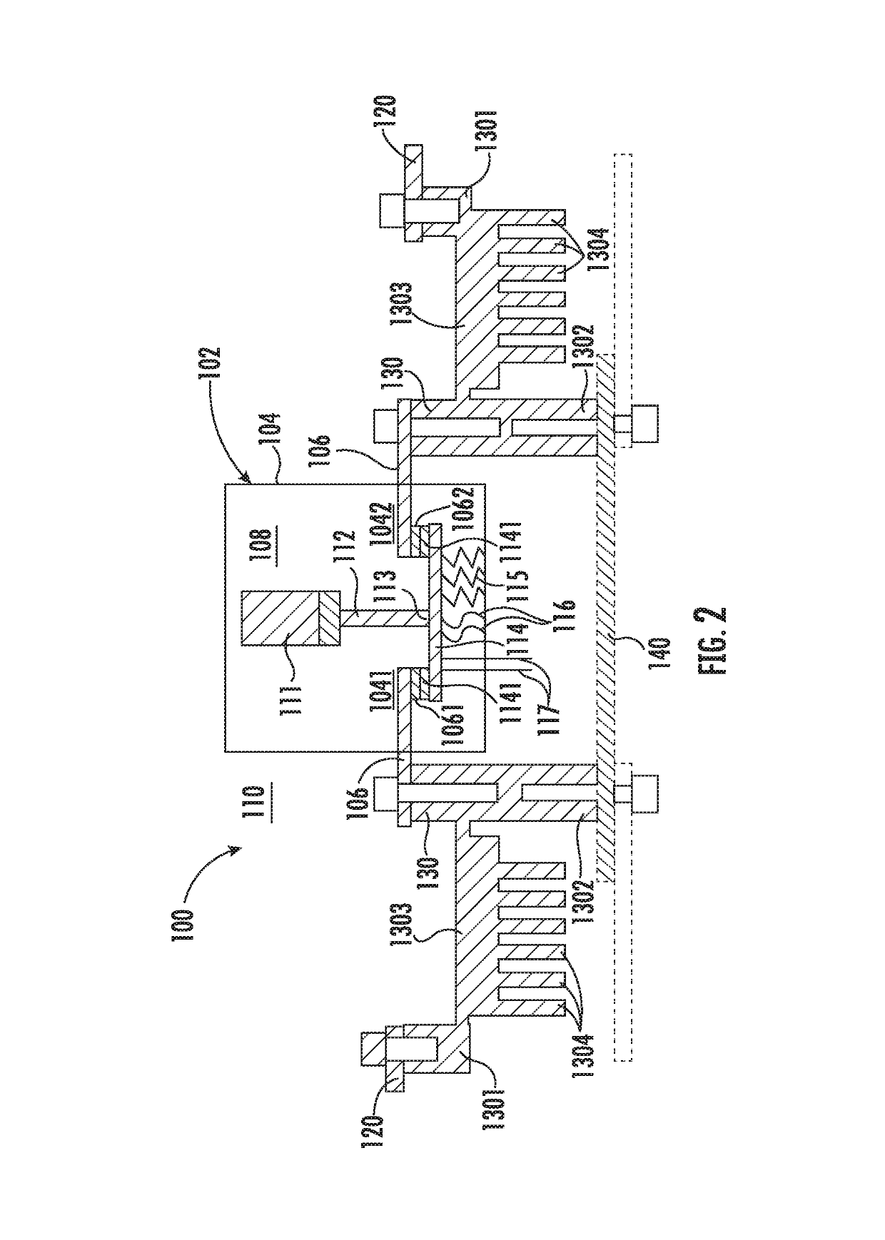
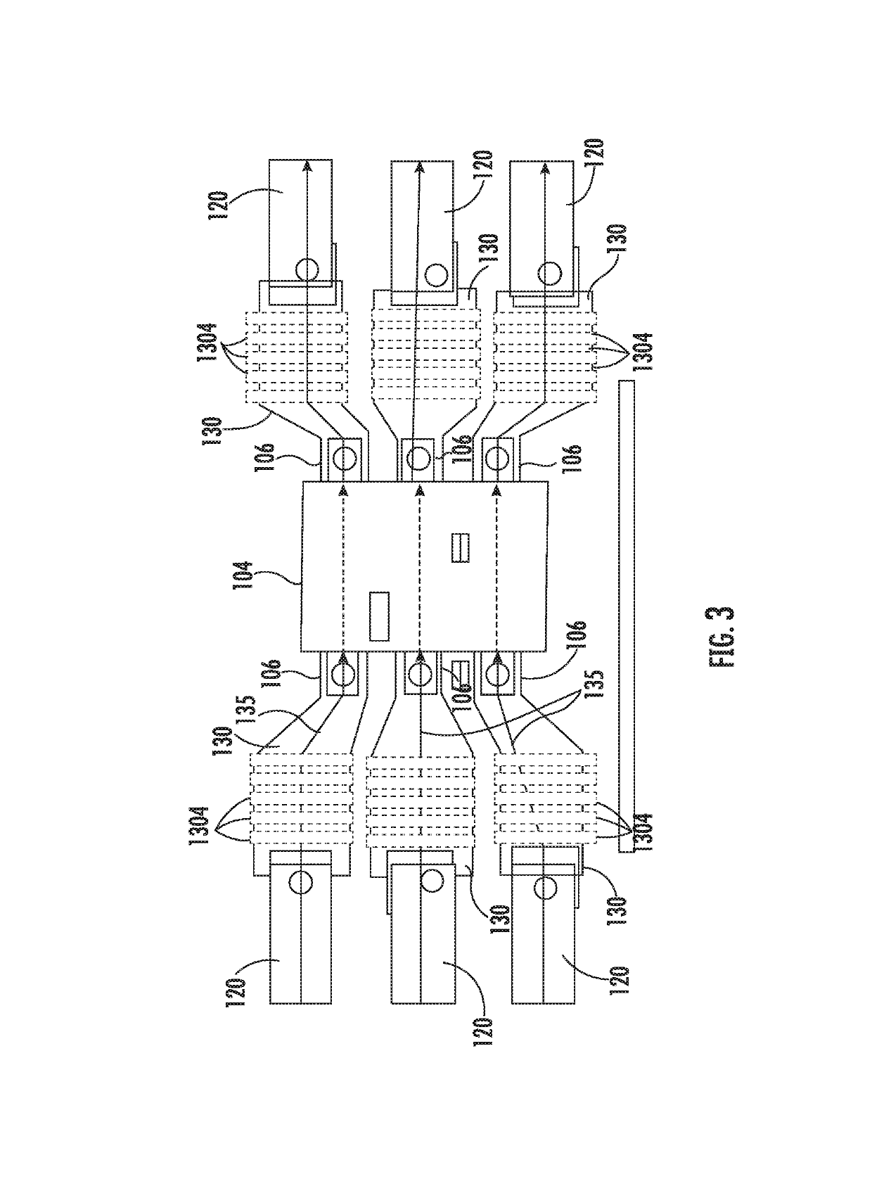
[0032]As will be described below, a contactor mounting post is provided with integral fins for cooling. The mounting post is bolted to a panel and a contactor and has a perpendicular bus bar with fins. An opposite end of the bus bar has another post to which output or input bus bars are bolted. In this manner, enhanced cooling is achieved. In addition, since current carrying interfaces are at least partially exposed, relatively easy cleaning of bus bar to post and contactor to post bolted joints is enabled.

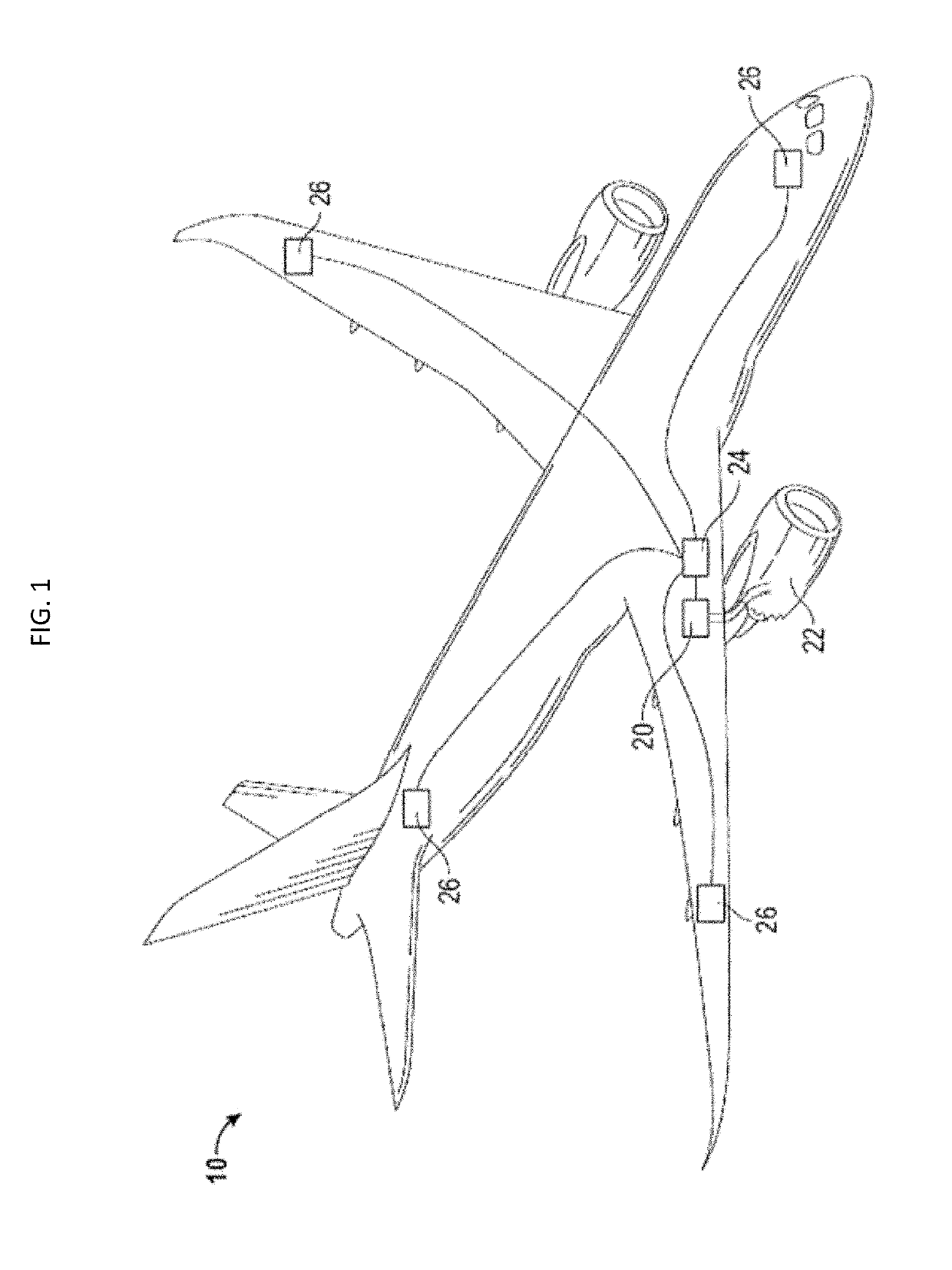
[0033]With reference to FIG. 1, an aircraft 10 is provided and includes an electrical power distribution system 20 which utilizes rotation within the jet engines 22 to generate either single phase or three phase electrical power. The power is sent to a panel box 24 that contains multiple electrical buses and contactor assemblies for controlling how the power is distributed throughout the aircraft 10. Through the use of the contactor assemblies, power may be controlled for each onb...


PUM


Abstract

A contactor assembly post is provided. The contactor assembly post includes a first portion electrically connected to an external bus bar at an exterior of an electrical contactor housing, a second portion electrically connected to an internal bus bar at the exterior of the electrical contactor housing, a third portion and fins. The internal bus bar is configured to extend into an interior of the electrical contactor housing to be electrically coupled to another internal bus bar. The third portion extends transversely between the first and second portions. The fins extend transversely from multiple points defined along a longitudinal axis of the third portion.

Description

BACKGROUND[0001]The following description relates to electrical contactors and, more particularly, to an electrical contactor mounting assembly with an integrated contactor mounting post that is capable of dissipating heat.[0002]Contactor assemblies are used in electrical applications, such as aircraft power distribution systems, where power and current flow control of a multi-phase power distribution system is required. A primary power distribution assembly typically has a panel on which several electrical contactors are mounted. Known mounting assemblies used to mount electrical contactors to the panels are constructed of thermally and electrically resistive materials, such as plastics, FR-4 or other woven resin fabric materials.[0003]Each of the contactors is connected to an electrical bus bar and allows current to flow through the contactor and the corresponding bus bar whenever the contactor is in a closed position. The electrical power and current flow through the contactors i...

Claims


Application Information

Patent Timeline
Patent Type & Authority Patents(United States)
IPC IPC(8): H02B1/56H01H1/62H01H9/52H01H50/12H01H50/14H01H50/54H01H51/06B60R16/03
CPCH02B1/56H01H1/62H01H9/52H01H50/12B60R16/03B64D2221/00H01H50/14H01H50/546H01H51/065
Inventor PAL, DEBABRATASEVERSON, MARK HAMILTON
Owner HAMILTON SUNDSTRAND CORP
Why Eureka
Try Eureka