

Vehicle protection apparatus
a technology for protecting equipment and vehicles, applied in the direction of deflectors, superstructure subunits, vehicle components, etc., can solve the problems of excessive force being applied to the vehicle, more prone to contact obstacles, and significant damage to the vehicl
- Summary
- Abstract
- Description
- Claims
- Application Information
AI Technical Summary
Benefits of technology
Problems solved by technology
Method used
Image

Examples
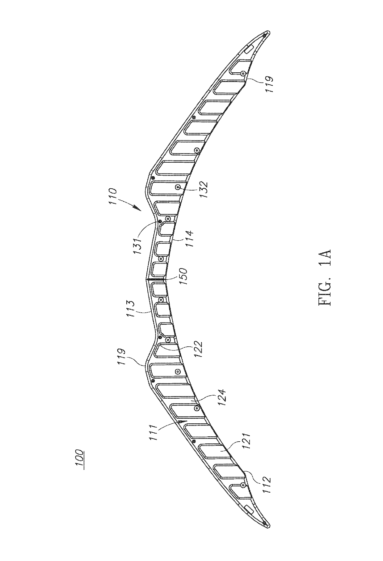
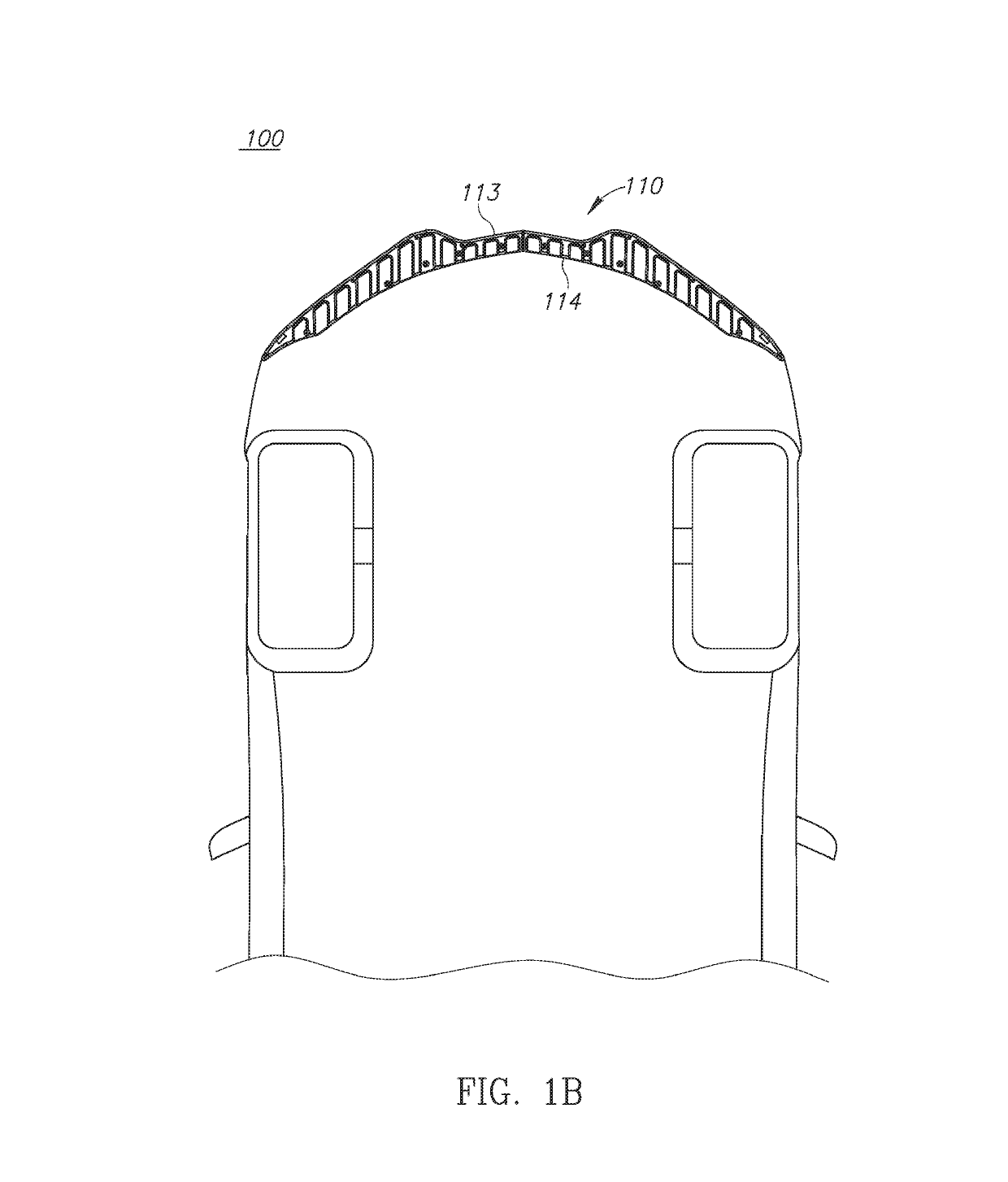
embodiment 100
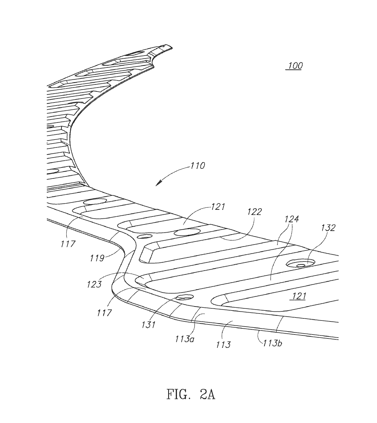
[0028]FIGS. 2A, 2B, and 2C illustrate different views of one portion of the protective panel 110 in accordance with FIG. 1 and embodiment 100. FIG. 2A illustrates a side profile and close up view of one possible embodiment of the protective panel 110. As illustrated, the first edge 113 is optionally composed of an edge profile 113a-n. The profile of the first edge 113 can be many different profiles. For example it may be a radius portion, an ellipse, angle or otherwise. In some embodiments the profile of the first edge 13 extends from the upper surface 112 to the lower surface 111 such that the upper portion of the first edge 113 is further away from the center of the panel than the lower portion of the first edge 113. In the depicted exemplary embodiment, the first edge 113 is composed of a first profile 113a and a second profile 113b which corresponds to an area perpendicular to the upper surface 112. In a preferred embodiment the first edge 113 may be in two sections, the first a...
embodiment 200
[0033]Referring now to FIG. 4, which illustrates another possible embodiment 200 of a protective panel 210 where the protective panel 210 is made of any number of sub-portions 210a-n. In some embodiments, it may be unnecessary to install a protective panel at one or more points along a single portion of the vehicle. For example, where only a limited portion of a bumper is likely to contact obstacles. Or, in other embodiments, extreme angles may make single piece protective panels impractical to design, manufacture, or ship. Or further still, for packaging or reasons of economy, or for any other reason, a user may wish to use a protective panel 210 where the panel is made of more than one individual part 210a-n. A multi-piece protective panel 210 may include, for example, and is not limited to, a center portion 210a, two off center portions 210b and two corner portions 210c. When installed, 210a may be located in the middle. 210b on either side of 210a, and 210c at the outer edges of...
PUM
 Abstract
Description
Claims
Application Information