Photovoltaic mounting system with locking connectors, adjustable rail height and hinge lock

a technology of photovoltaic panels and mounting systems, applied in the direction of fastening means, rod connections, haberdashery, etc., can solve the problems of large skill and precision in the installation process, and the conventional installation method consumes many man-hours of installation labor, and achieves cost-effective effects

Inactive Publication Date: 2009-11-19
POWERMOUNT SYST +1
View PDF18 Cites 273 Cited by
  • Summary
  • Abstract
  • Description
  • Claims
  • Application Information

AI Technical Summary

Benefits of technology

[0010]The apparatuses and methods disclosed herein are more cost-effective means and method of installing PV panel arrays. The present invention includes a cam-actuated connector to fasten perpendicular mounting components used to install PV panels, and a PV panel mounting rail that a...

Problems solved by technology

The conventional methods of installation generally consume many man-hours of installation labor and must be placed in precise locat...

Method used


Image

  • Photovoltaic mounting system with locking connectors, adjustable rail height and hinge lock
  • Photovoltaic mounting system with locking connectors, adjustable rail height and hinge lock
  • Photovoltaic mounting system with locking connectors, adjustable rail height and hinge lock

Examples


Embodiment Construction

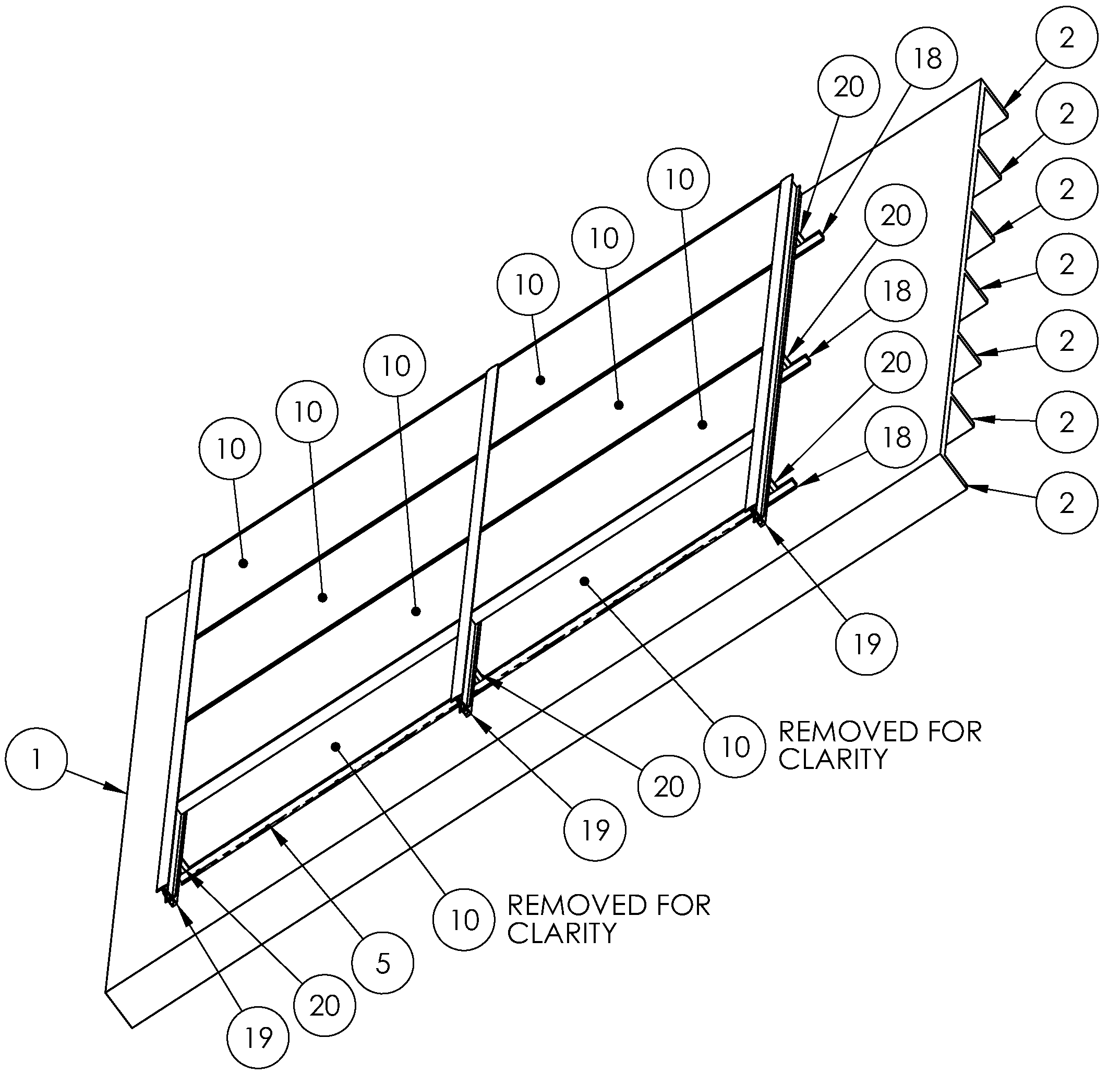
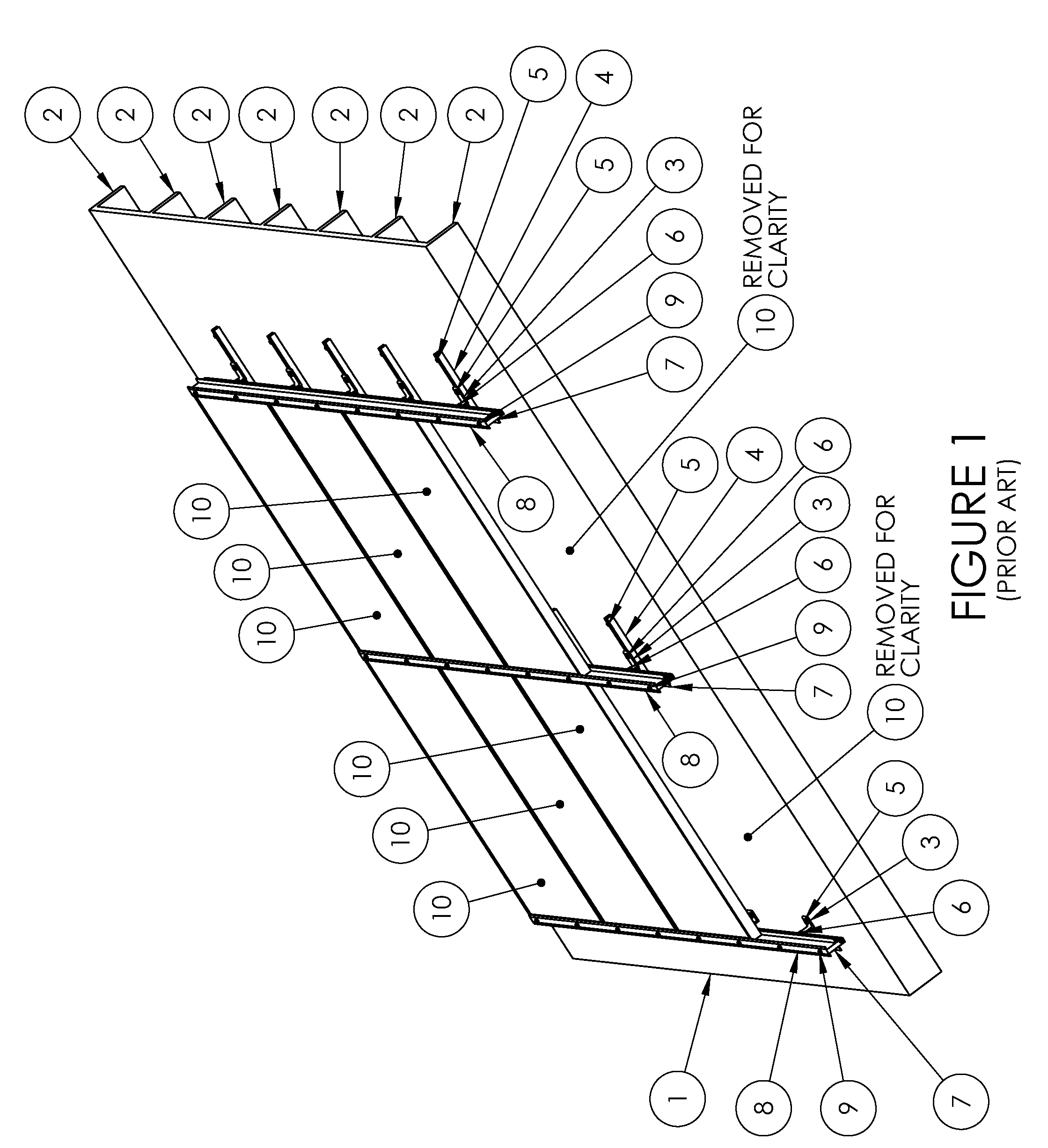
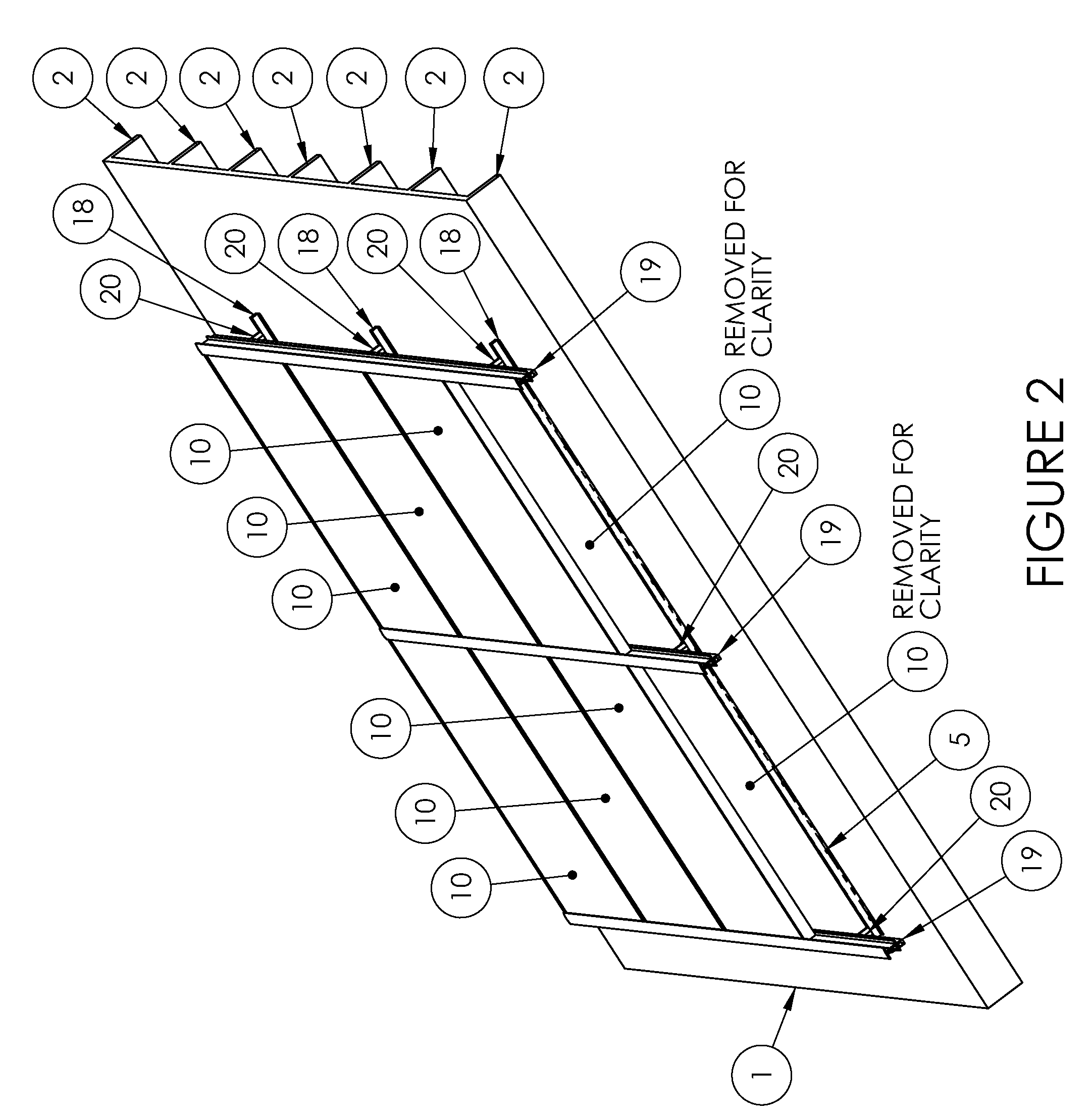
[0058]Referring to FIG. 1, a portion of a conventional residential roof structure 1 is shown, and presents a common mounting medium for which the present invention is particularly suited. The portion shown in FIG. 1 is typical of a residential roof structure, having support beams over which one or more weatherproof sheets is attached, such as plywood and shingles. Of course, the roof structure 1 is merely one example of a structure to which the present invention can be mounted, as will be understood by the person having ordinary skill in the design and installation of photovoltaic electrical systems. The residential roof structure 1 is described herein, but it will be understood by the person of ordinary skill that other structures can be substituted for the structure 1, including without limitation a commercial, institutional or agricultural roof structure, a planar structure built specifically to support a PV array, a wall or ground-mounted area, or any other stable, fixed structu...


PUM

PropertyMeasurementUnit
Forceaaaaaaaaaa
Sizeaaaaaaaaaa
Radiusaaaaaaaaaa

Abstract

A cam-actuated connection device joins rail mounting members of a photovoltaic panel array. The connection device slides within channels of mounting members until the members are in a properly positioned grid. When in position, the connection device is rotated to lock the mounting members in a rigid grid network. The connecting device can be subsequently loosened, repositioned and locked into position. The rail-mounting members create a grid for installation of multiple PV panels. The mounting rail allows the unit to remain relatively compact in nature but still covers a wide range of PV panel thicknesses. The rail system has a hinged connection with the mounting rail that allows an installer to assemble the module in a near perpendicular fashion to the mounting rail, make the required electrical connections and then lower the PV module into its working position. The unit is then locked into its working position.

Description

CROSS-REFERENCES TO RELATED APPLICATIONS[0001]This application claims the benefit of U.S. Provisional Application No. 61 / 054,296 filed May 19, 2008, and U.S. Provisional Application No. 61 / 090,055 filed Aug. 19, 2008, both of which are incorporated herein by reference.STATEMENT REGARDING FEDERALLY-SPONSORED RESEARCH AND DEVELOPMENT[0002](Not Applicable)REFERENCE TO AN APPENDIX[0003](Not Applicable)BACKGROUND OF THE INVENTION[0004]1. Field of the Invention[0005]This invention relates generally to the mounting of photovoltaic panels on rooftops and other structures, and more particularly to hardware to facilitate the mounting of the panels.[0006]2. Description of the Related Art[0007]Photovoltaic (herein, “PV”) mounting grids are commonly used to mount PV panel arrays to building structures, ground mounted systems and a large variety of alternate configurations. In one common configuration, a rail and a cleat are mounted, for example to a rooftop of a home, and the panel arrays are mo...

Claims


Application Information

Patent Timeline
IPC IPC(8): E04D13/18B23P11/00F16D1/12
CPCF16B2/185Y10T24/44573F16B5/0635F16B5/0685F16B7/0493F16B7/182F24J2/5205F24J2/5207F24J2/5211F24J2/5254F24J2/5258F24J2/526F24J2/5264F24J2002/4665F24J2002/4669F24J2002/5226Y02B10/12Y02E10/47Y02E10/50H02S20/00H02S20/23Y10T29/49948Y10T403/32426F16B5/0032F24S25/20F24S25/33F24S25/35F24S25/632F24S25/636F24S25/65F24S25/70F24S2025/6004F24S2025/6006F24S2025/807H02S20/30Y02B10/10
Inventor ABBOTT, RONALD E.KENT, PERRY L.ABBOTT, RYAN D.
Owner POWERMOUNT SYST
Why Eureka
Try Eureka