Bracelet clasp
a bracelet and clasp technology, applied in the field of clasps, can solve the problems of not being able to completely secure the locking mechanism, it is not easy for users to operate such a mechanism, etc., and achieve the effect of simple and fast adjustment and simple implementation
- Summary
- Abstract
- Description
- Claims
- Application Information
AI Technical Summary
Benefits of technology
Problems solved by technology
Method used
Image
Examples
first embodiment
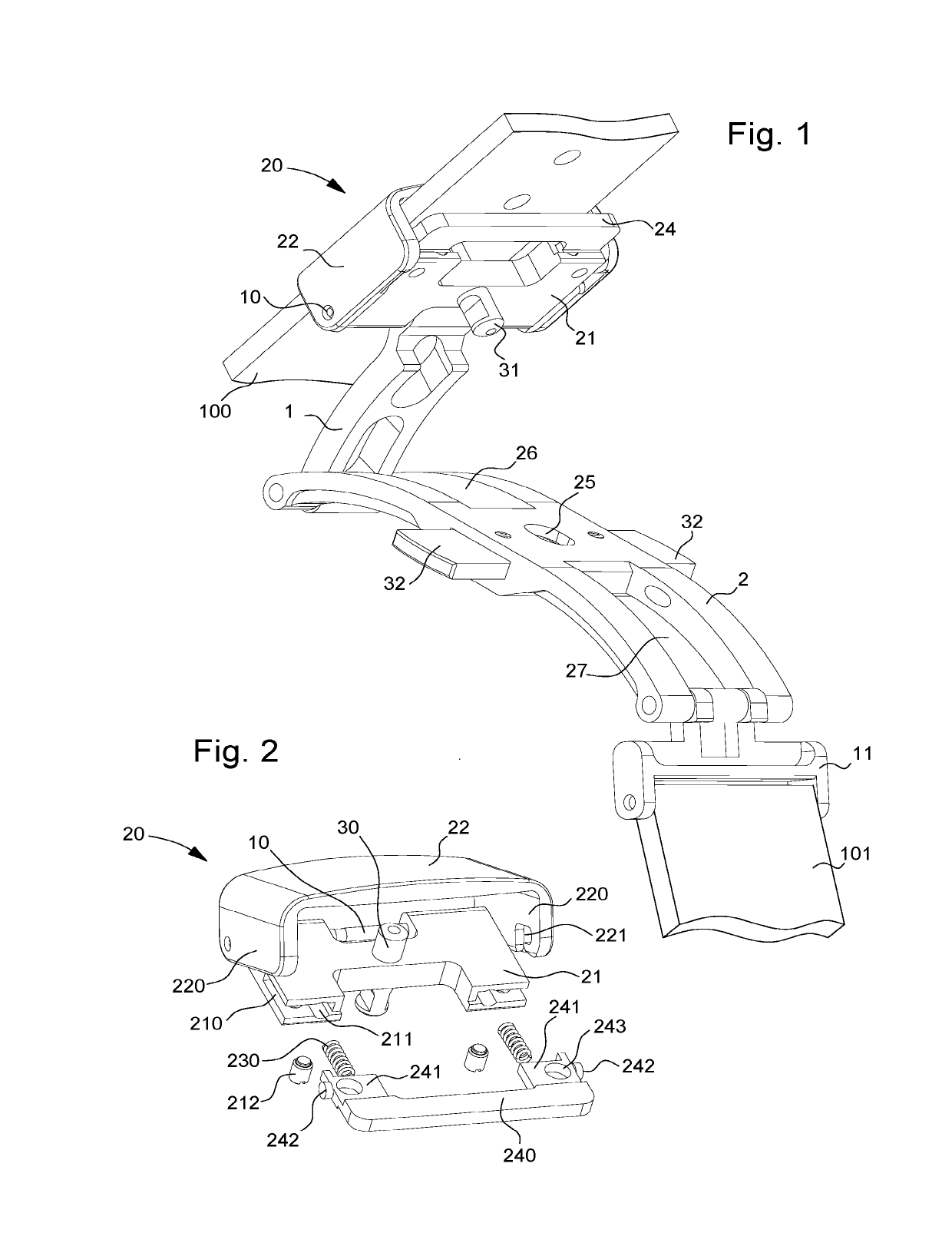
[0045] the invention concerns a bracelet clasp, of the type with a deployment buckle, including at least first and second strips, the first strip 1 being hinged to the second strip 2 by a first end, between a closed position, called the wearing position, in which the first strip 1 is folded onto the second strip 2, and an open position, in which the first strip 1 is released from the second strip 2.
[0046]First strip 1 carries, at a second end, a member 20 for securing a first bracelet strand 100, a second bracelet strand 101 being at least indirectly connected to second strip 2 by means of an attachment link 11 for example, first strip 1 including first locking means capable of holding first strip 1 in its closed position.
[0047]Strands 100, 101 may be manufactured in materials such as leather, fabric, canvas, or any other material known to those skilled in the art for producing bracelets or belts.
[0048]The first locking means may be formed, for example, by at least one spring catch ...
second embodiment
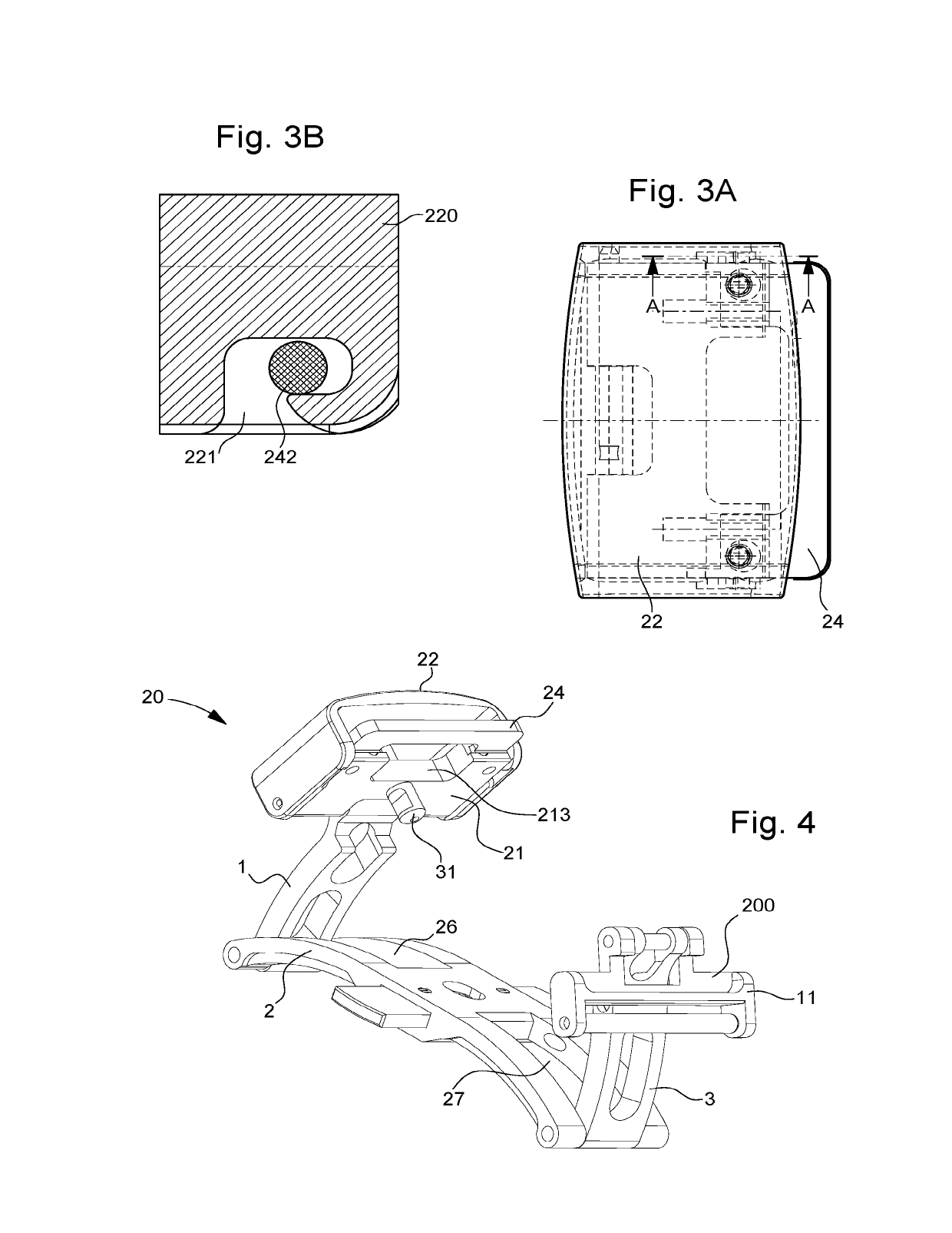
[0065]According to the invention, the bracelet clasp, of the deployment buckle type, includes first, second and third strips, the first strip 1 being hinged to the second strip 2 by a first end, and the third strip 3 being hinged to second strip 2 by the second end, opposite the first end.
[0066]First strip 1 and third strip 3 can change from a closed position, called the wearing position, in which first strip 1 and third strip 3 are folded onto second strip 2, to an open position in which first strip 1 and third strip 3 are released from second strip 2.
[0067]First strip 1 carries, at a second end, a member 20 for securing a first bracelet strand 100, a second bracelet strand 101 being at least indirectly connected to second strip 2, first strip 1 including first locking means 10 capable of holding first strip 1 in its closed position.
[0068]As can be observed in FIG. 4, securing member 20 includes identical means of adjusting the length of first strand 100 to those present in the fir...
third embodiment
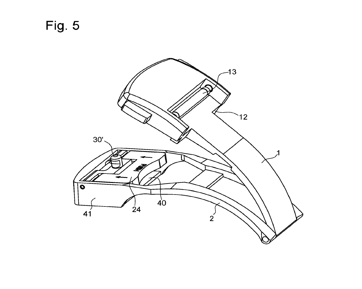
[0075]According to this third embodiment, the clasp includes a first strip 1 hinged to a second strip 2 by a first end, between a closed position, called the wearing position, in which first strip 1 is folded onto second strip 2, and an open position, in which first strip 1 is released from second strip 2.
[0076]Second strip 2 carries, at a second end, a member 20 for securing a first bracelet strand 100, a second bracelet strand may be at least indirectly connected to first strip 1 by means of an arbor 13 for example, first strip 1 including first locking means capable of holding first strip 1 in its closed position.
[0077]As can be observed in FIG. 5, the second strip includes at its second end a bridge 40 for the passage of first strand 100. Bridge 40 may be pierced, depending on the material used to manufacture the strips of the clasp, in order to reduce manufacturing costs.
[0078]The first locking means may be formed, for example, by at least one spring catch 32 configured to hold...
PUM
 Abstract
Description
Claims
Application Information
 - R&D
- Intellectual Property
- Life Sciences
- Materials
- Tech Scout
- Unparalleled Data Quality
- Higher Quality Content
- 60% Fewer Hallucinations
Browse by: Latest US Patents, China's latest patents, Technical Efficacy Thesaurus, Application Domain, Technology Topic, Popular Technical Reports.
© 2025 PatSnap. All rights reserved.Legal|Privacy policy|Modern Slavery Act Transparency Statement|Sitemap|About US| Contact US: help@patsnap.com


