Stop for shoe binding device

a technology of shoe binding and stop, which is applied in the field of shoe binding, can solve the problems of difficult maneuverability, unusable, and inconvenient use, and achieve the effect of convenient maneuverability and optimal safety

Active Publication Date: 2019-05-21
SKIS ROSSIGNOL
View PDF11 Cites 0 Cited by
  • Summary
  • Abstract
  • Description
  • Claims
  • Application Information

AI Technical Summary

Benefits of technology

[0007]A first object of the present invention is to provide a solution for fastening a boot on a sliding board, in particular on a touring ski, that guarantees optimal safety for the skier in the event of a fall.
[0008]A second object of the present invention is to provide a boot fastening solution that is simple, easy to maneuver, not bulky, economical and lightweight.
[0009]These aims can be achieved via a toe piece for a device for fastening a boot on a sliding board, comprising a base intended to be fixed to the sli

Problems solved by technology

One drawback with such existing toe pieces is their lack of safety should a skier fall, particularly in the case of a twisting fall of the skier in an alpine ski downhill situation, involving a twisting movement of the boot relative to the ski during which the boot remains captive in the toe

Method used


Image

  • Stop for shoe binding device
  • Stop for shoe binding device
  • Stop for shoe binding device

Examples


first embodiment

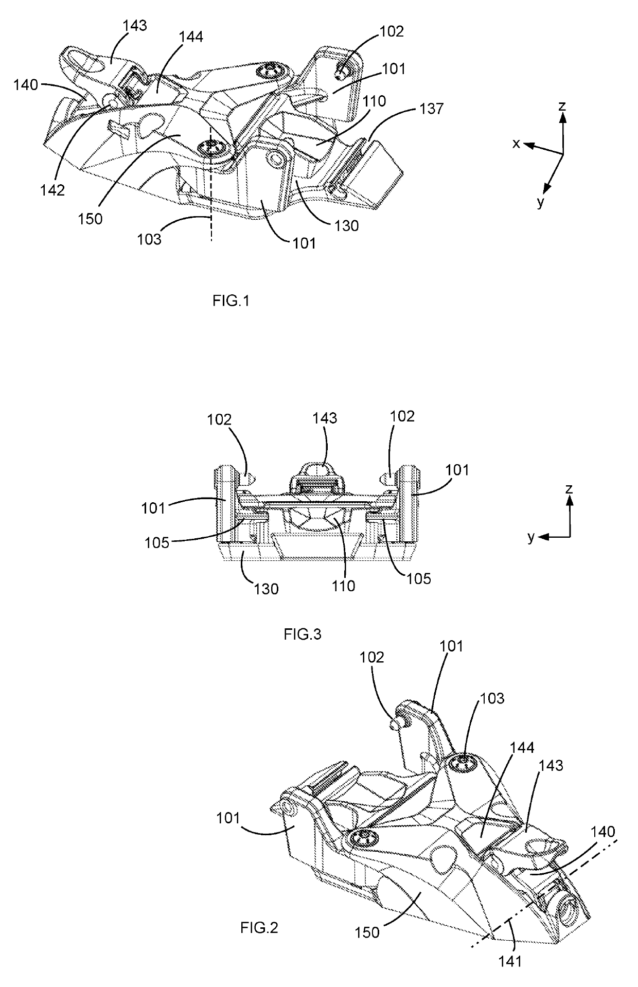
[0044] the toe piece comprises a base 130 intended to be fixed to a sliding board, and mobile elements arranged on this base 130. It also comprises a top cap 150 positioned in front of the jaws and covering all or part of the mobile elements. It also comprises a substantially cylindrical recess 137 in the rear part, provided to receive a connection pin of a boot, not represented.

[0045]The toe piece first of all comprises two rigid jaws 101, arranged laterally and in the rear part of the toe piece. Each jaw 101 comprises a retaining element 102 intended to ensure the retention of the boot when the jaw is in a closed position, which will be detailed later. The retaining element 102 takes the form of a holding pin intended to engage in lateral openings formed in the front part of the boot. It is thus oriented toward the center of the toe piece, in a substantially transverse direction. Each jaw extends substantially longitudinally on each side of the toe piece, so as to be able to coope...

second embodiment

[0069]FIGS. 18 to 27 illustrate the invention.

[0070]To attach the ski boot (not represented), two jaws 8, 9 are provided, these jaws being arranged so as to be rotationally mobile about rotation axes of the jaws 10, 11 in relation to a baseplate or base 3.

[0071]These jaws 8, 9 that can pivot have an attachment arm 12, 13 each extending from the rotation axes of the jaws 10, 11 to a link-jaw attachment points 14, 15. A link 16 is articulated at these link-jaw attachment points 14, 15, said links being linked to one another by bolts (not represented) engaged in the link-jaw attachment points 14, 15.

[0072]The articulated connection of the jaws 8, 9 via the rotation axes 10, 11 of the jaws with the baseplate 3 resting below and via the link-jaw attachment points 14, 15 with the link 16 allows the link to slide over a line linking the link-jaw attachment points 14, 15.

[0073]A holding arm 17, 18 at the end of which a holding pin 19, 20 is respectively provided, extends on the side of the ...


PUM


Abstract

A toe piece for a device for fastening a boot on a sliding board, having a base (130; 3) intended to be fixed to the sliding board, two lateral jaws (101; 8, 9), each mounted to be rotationally mobile on the base (130; 3) about a substantially vertical rotation axis (103; 10, 11), so as to occupy a closed position to hold a boot and a separated position to release or receive a boot, and a pusher (110; 35) having two lateral trig surfaces (114; 24, 25) each cooperating with a respective ramp (104; 22, 23) of each jaw (101; 8, 9), this pusher being linked to the base by a trig spring (112; 36), and two links (120; 28, 29) each linked to a jaw by a first lateral axis (123; 14, 15) and linked together by at least one central axis (125; 32).

Description

[0001]This application claims priority of the application in Germany number DE102016013104.7 filed on Nov. 2, 2016, which is hereby incorporated by reference in its entirety in this application.BACKGROUND ART[0002]The invention relates to a toe piece of a device for fastening a boot on a sliding board. This toe piece is particularly suited to ski touring. It relates also to a device for fastening a boot on a sliding board and a sliding board as such equipped with such a fastening device and / or such a toe piece.[0003]The document EP-A1-2353673 describes a toe piece of a device for fastening a boot on a touring ski. The front fastening of the boot rests on two jaws of the toe piece articulated on longitudinal pivoting axes relative to a base of the toe piece intended to be fastened to the touring ski. Each jaw comprises retaining elements intended to cooperate with the touring ski boot. The two jaws are articulated by a spring system in order to occupy a so-called closed stable first ...

Claims


Application Information

Patent Timeline
IPC IPC(8): A63C9/00A63C9/08A63C9/22A63C9/085A63C9/086
CPCA63C9/0805A63C9/085A63C9/086A63C9/22A63C9/08521A63C9/08564A63C9/08571A63C9/0807
Inventor ZOOR, REINHOLDGILLIN, JEROME
Owner SKIS ROSSIGNOL
Why Eureka
Try Eureka