Tray support inserts for chemical reactor vessels and methods of use

a technology for chemical reactors and inserts, which is applied in the direction of mechanical equipment, chemistry apparatus and processes, hydrocarbon oil cracking, etc., can solve the problems of high temperature and pressure, damage to reactor components, and large volume of chemical reactor vessels, and achieves intense heat and heavy weight

Active Publication Date: 2019-05-21
SHELL USA INC
View PDF1 Cites 0 Cited by
  • Summary
  • Abstract
  • Description
  • Claims
  • Application Information

AI Technical Summary

Benefits of technology

[0004]The invention provides a hydrocarbon chemical (hydrotreating / processing) reactor vessel having a tray support insert which can support one or more trays. In described embodiments, the tray support insert can support a number of trays or beds within the reactor chamber while permitting relative movement between a tray and insert and the walls of the surrounding vessel. The tray support insert allows for expansion and contraction of metal components within the reactor in response to changes in temperature and pressure. In accordance with a particular described embodiment, the tray support insert is used to support the quench section of the reactor within the reactor chamber. When the tray support insert is used, the quench section is seated at a heightened elevation within the reactor chamber as compared to a configuration in which the tray support insert is not used. Thus, use of the tray support insert permits the quench section, including quench tray and high dispersion tray, of an existing reactor to be moved axially upwardly within the reactor chamber and yet still be supported in a robust manner which can handle heavy weight and intense heat. Movement of the quench section will reduce the size of the reactor chamber which can contain an upper bed of catalyst but increase the size of the reactor chamber which can contain a lower bed of catalyst, thereby accommodating particular changes to the chemical processes which can be carried out within the reactor vessel.
[0006]An exemplary tray support insert is described which includes a support grid skirt and a catalyst support grid ring. The described support grid skirt includes an annular skirt frame and support blocks that extend axially downwardly from the skirt frame. Support members extend axially upwardly from the skirt frame. The described catalyst support grid ring is stacked on top of the support grid skirt. Both the support grid skirt and catalyst support grid ring present lips or ledges upon which one or more trays can be supported. Use of the tray support insert allows spacing between the tray and the interior surface of the reactor chamber which will accommodate expansion, contraction and other movement of the trays within the reactor chamber during use. The support grid skirt and catalyst support grid ring are each preferably formed of separate arcuate segments so that they can be disassembled and the segments easily disposed into an opening in the reactor vessel. Once inside the reactor vessel, the support grid skirt and catalyst support grid ring can be assembled to form complete annular structures.

Problems solved by technology

Chemical reactor vessels are very large and heavy, and, as a result, are often built in-place with rolled or forged steel.
During typical operation, the contents of a chemical reactor are subjected to high temperatures and pressures.
Trays supported within the reactor chamber can expand or contract thermally, shifts or otherwise move, resulting in damage to reactor components.

Method used


Image

  • Tray support inserts for chemical reactor vessels and methods of use
  • Tray support inserts for chemical reactor vessels and methods of use
  • Tray support inserts for chemical reactor vessels and methods of use

Examples


Embodiment Construction

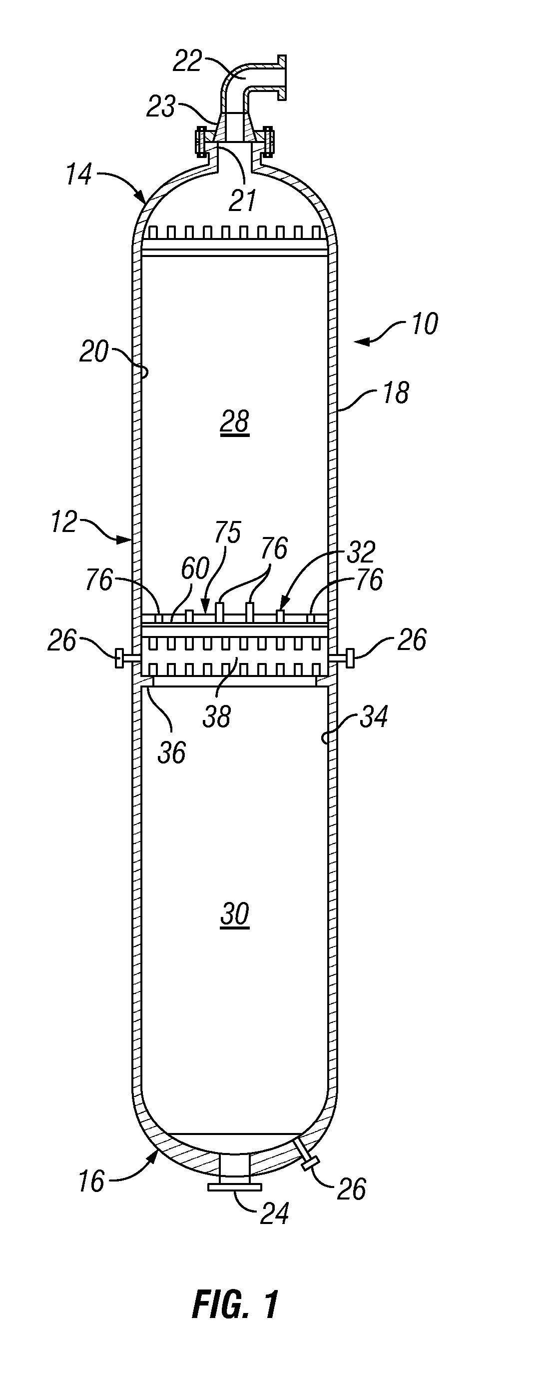
[0020]FIG. 1 depicts an exemplary chemical reactor vessel 10 constructed in accordance with the present invention. The reactor vessel 10 is preferably a catalytic reactor which will contain one or more trays of catalyst material. The reactor vessel 10 includes a central reactor barrel 12, top head portion 14 and bottom portion 16. The reactor vessel 10 includes a reactor housing 18 which is typically formed of forged carbon steel. The reactor housing 18 defines a reactor chamber 20 within. The central reactor barrel 12 of the reactor vessel 10 is typically cylindrical in shape resulting in the reactor wall 18 there having a circular cross-sectional shape. A feed inlet 22 allows chemical feed to be treated to enter the reactor chamber 20. In the depicted embodiment, the feed inlet 22 is located in the top head portion 14 of the reactor vessel 10. The feed inlet 22 is secured within a removable cover 23 that is affixed to a restricted diameter opening 21 using threaded connectors. A f...


PUM

PropertyMeasurementUnit
thicknessaaaaaaaaaa
thicknessaaaaaaaaaa
thicknessaaaaaaaaaa

Abstract

A tray support insert and method of use for supporting one or more trays within a reactor chamber. The tray support insert includes at least one annular member which rests upon a support shoulder within the reactor chamber.

Description

FIELD OF THE INVENTION[0001]The invention relates generally to the arrangements for supporting trays of chemical or materials within chemical reactor vessels.BACKGROUND OF THE INVENTION[0002]Hydrotreating / hydroprocessing chemical reactor vessels, including catalytic reactors, are used extensively in many industries, including the petrochemical industry. Chemical reactor vessels are very large and heavy, and, as a result, are often built in-place with rolled or forged steel. A typical catalytic reactor is generally cylindrical and can be from about 10 to about 150 feet tall and 1-25 feet wide with walls having a thickness that can vary from about 2 inches to about 16 inches. A fluid feed is flowed into the upper end of the reactor vessel and through a series of trays, allowing catalyzed chemical processes to take place. During typical operation, the contents of a chemical reactor are subjected to high temperatures and pressures. During a typical catalytic reaction operation, the reac...

Claims


Application Information

Patent Timeline
Patent Type & Authority Patents(United States)
IPC IPC(8): B01J8/02B01J8/04C10G45/00F16M13/02C10G47/02
CPCB01J8/02B01J8/0278B01J8/0453B01J8/0492C10G47/02F16M13/02C10G45/00B01J2219/00024B01J2208/00884B01J2208/027
Inventor MAAS, EDWINSCHILTHUIZEN, REMCO
Owner SHELL USA INC
Why Eureka
Try Eureka