Elbow prosthesis

a technology for elbows and prostheses, applied in the field of elbow prostheses, can solve the problems of complex devices of joint prostheses, and achieve the effects of safe and cost-effective, normal lifestyle, and convenient assembly

Inactive Publication Date: 2019-05-28
TECRES SPA
View PDF6 Cites 1 Cited by
  • Summary
  • Abstract
  • Description
  • Claims
  • Application Information

AI Technical Summary

Benefits of technology

[0011]Another object of the present invention is to provide a prosthesis for the elbow joint which allows joint functionality to be maintained, ensuring that the patient has a substantially normal lifestyle.
[0012]Yet another object of the present invention is to provide a prosthesis for the elbow joint, which is composed of a reduced number of components.
[0013]Not latter object of the present invention is to provide a prosthesis for the elbow joint, which is easy to assemble.
[0014]Another purpose of the present invention is to provide a prosthesis for the elbow joint that is safe and cost-effective.

Problems solved by technology

Currently for the treatment of lesions of the elbow joint there are joint prostheses which are very complex devices, equipped with numerous components that 15 require long times for the assembly and implantation in the limb of a patient.

Method used


Image

  • Elbow prosthesis
  • Elbow prosthesis
  • Elbow prosthesis

Examples


first embodiment

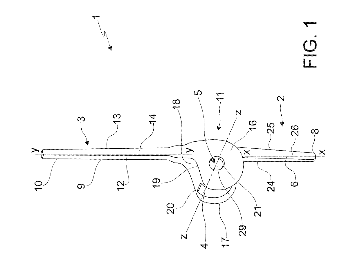
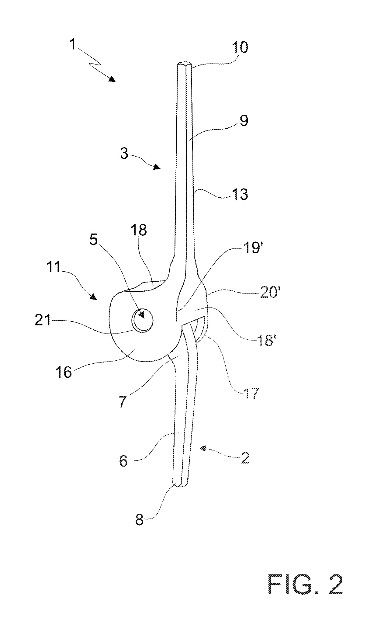
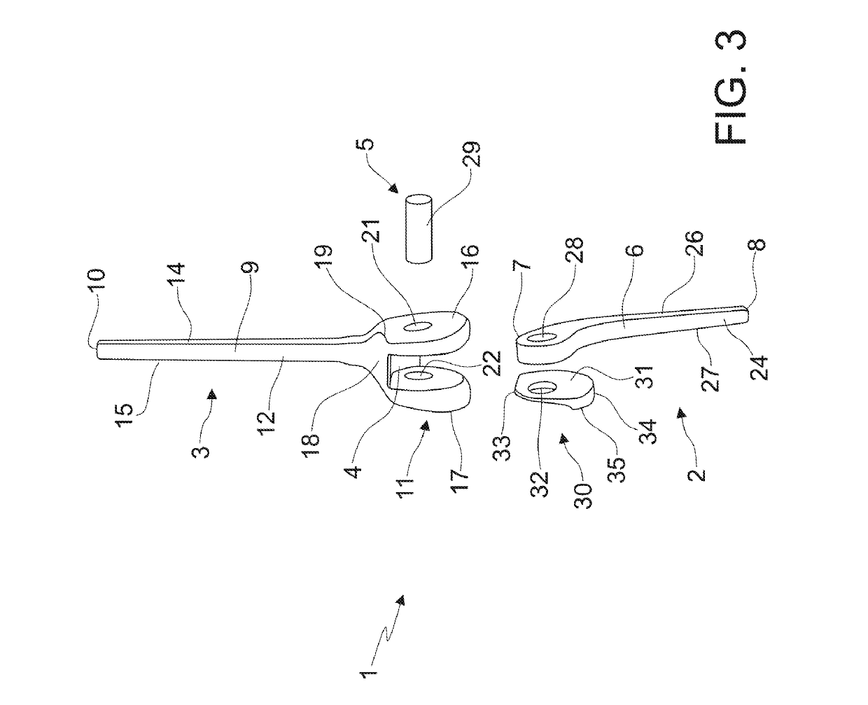
[0036]The prosthesis 1 according to the present invention comprises at least one ulnar section 2, at least one humeral section 3 delimiting an engagement seat 4 and articulation means 5, at such an engagement seat 4, intended to make the engagement and the articulation between the ulnar section 2 and the humeral section 3.

[0037]More particularly, the ulnar section 2 has a stem portion 6, which is extended along a substantially longitudinal axis x-x between a proximal end 7 and a distal end 8.

[0038]The humeral section 3 has a stem portion 9, which extends along a substantially longitudinal axis y-y between a proximal end 10 and a distal end 11. The distal end 11 of the humeral section 3 delimits, as stated above, an engagement seat 4 with the proximal end 7 of the ulnar section 2.

[0039]The articulation means 5 between the distal end 11 of the humeral section 3 and the proximal end 7 of the ulnar section 2, as will be made clearer hereafter, are, in use, arranged in the engagement sea...

second embodiment

[0069]In this second embodiment, as can be noted, the gap delimited by the through opening 28-32 of the ulnar section has a constant cross section.

[0070]It has thus been seen how the prosthesis described above clearly solves the aforementioned technical problems, since it has a configuration totally alternative with respect to the conventional prostheses, comprises a small number of components and is also very simple to assemble.

[0071]Such a prosthesis, moreover, comprising a stem portion both on the ulnar section 2 and on the humeral section 3, allows it to be in turn inserted in respective bone portions of a patient to be treated, thus ensuring joint mobility.

[0072]The prosthesis for an elbow joint1 described above can undergo numerous modifications and variants within the scope of protection of the following claims.

[0073]As can be seen, for example in figure 7, both the ulnar section 2 and the humeral section 3 comprise a stiffening core, preferably made from metallic material, w...


PUM


Abstract

The present invention concerns an elbow prosthesis, including: at least one ulnar section, including a stem portion extending along a substantially longitudinal axis (x-x) between a proximal end and a distal end; at least one humeral section, including a stem portion extending along a substantially longitudinal axis (y-y) between a proximal end and a distal end, the distal end of the humeral section delimiting an engagement seat with the proximal end of the ulnar section; articulation pin between the distal end of the humeral section and the proximal end of the ulnar section, available along an axis (z-z) perpendicular with respect to the substantially longitudinal axis (y-y) of the humeral section. The proximal end of the ulnar section is engageable in the housing seat.

Description

TECHNICAL FIELD OF THE INVENTION[0001]The present invention concerns a prosthesis for the elbow joint.STATE OF THE PRIOR ART[0002]The elbow joint, although it is often considered to be a single joint, comprises three separate articulations, associated with a single capsule. These are the humeroradial articulation, the humeroulnar articulation, which allows the bending and extending movements of the forearm on the arm, and the proximal radioulnar articulation, which allows the prono-supination of the hand.[0003]The present invention regards a prosthesis that affects the humeroulnar joint.STATE OF THE PRIOR ART[0004]Currently for the treatment of lesions of the elbow joint there are joint prostheses which are very complex devices, equipped with numerous components that 15 require long times for the assembly and implantation in the limb of a patient.[0005]The U.S. Pat. No. 3,816,854 discloses a prosthesis for total replacement arthroplasty of the elbow joint consisting of a hinge joint...

Claims


Application Information

Patent Timeline
Patent Type & Authority Patents(United States)
IPC IPC(8): A61F2/38A61F2/30
CPCA61F2/3804A61F2/3094A61F2002/3813A61F2002/30624A61F2002/30472A61F2002/30433A61F2002/3822A61F2002/3831
Inventor FACCIOLI, GIOVANNISOFFIATTI, RENZO
Owner TECRES SPA
Why Eureka
Try Eureka