Slide rail mechanism

a technology of sliding rail and sliding frame, which is applied in the mounting of support structures, domestic applications, servers, etc., can solve the problems of limited use of tool-free slide rail mounting frames for servers, and achieve the effect of improving the support capability of slide rails

Active Publication Date: 2019-06-04
KING SLIDE WORKS CO LTD +1
View PDF16 Cites 21 Cited by
  • Summary
  • Abstract
  • Description
  • Claims
  • Application Information

AI Technical Summary

Benefits of technology

[0004]An objective of the present invention is to provide a slide rail mechanism capable of being mounted to a front post and a rear post of a rack by a single person in front of the rack, and capable of improving support capability of a slide rail.
[0005]Another objective of the present invention is to provide a slide rail mechanism capable of being mounted to racks with different depths through one-man operation, and capable of improving support capability of a slide rail.

Problems solved by technology

However, the design disclosed in the prior art is limited to a length of the outer rail and adjustable degree of a bracket cooperated with the outer rail, such that usage of the tool-free slide rail mounting frame for server is limited accordingly.

Method used


Image

  • Slide rail mechanism
  • Slide rail mechanism
  • Slide rail mechanism

Examples


Embodiment Construction

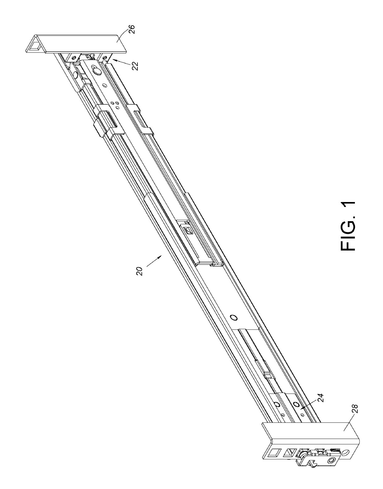
[0049]As shown in FIG. 1, a slide rail mechanism 20 of an embodiment of the present invention is configured to be mounted to a first post 26 and a second post 28 of a rack respectively through a first bracket 22 and a second bracket 24.

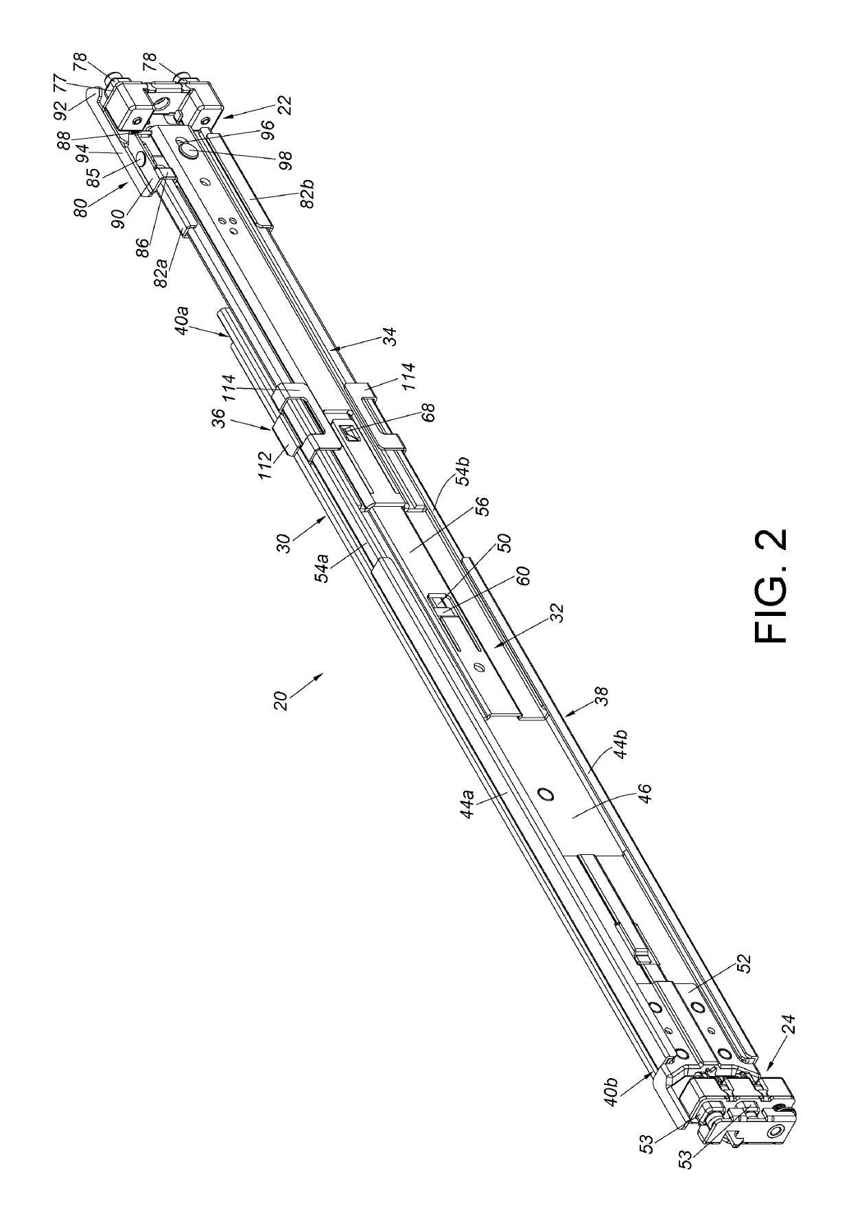
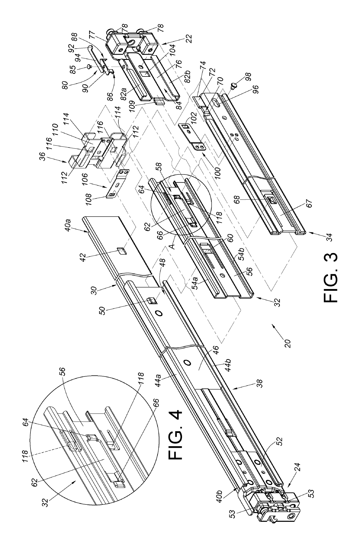
[0050]As shown in FIG. 2 and FIG. 3, the slide rail mechanism 20 comprises a rail member 30, a first supporting frame 32, a second supporting frame 34, the first bracket 22 and a reinforcing member 36. Preferably, the slide rail mechanism 20 further comprises a supporting rail 38.

[0051]The rail member 30 has a first end part 40a and a second end part 40b located opposite to the first end part 40a. The rail member 30 further comprises a first engaging structure 42 located between the first end part 40a and the second end part 40b.

[0052]The supporting rail 38 is connected, such as fixedly connected, to a back side of the rail member 30, such that the supporting rail 38 can be seen as a portion of the rail member 30. For example, the supporting rail 38 ...


PUM


Abstract

A slide rail mechanism includes a rail member, a first supporting frame, a second supporting frame, a bracket and a reinforcing member. The first supporting frame is movable relative to the rail member. The second supporting frame is movable relative to the first supporting member. The bracket and the second supporting frame are movable relative to each other. The reinforcing member is configured to be detachably engaged with the first supporting frame. Wherein, the rail member includes a first engaging structure, and the reinforcing member includes a second engaging structure. The reinforcing member is configured to be engaged with the first engaging structure through the second engaging structure.

Description

BACKGROUND OF THE INVENTION1. Field of the Invention[0001]The present invention relates to a slide rail mechanism, and more particularly, to a slide rail mechanism capable of being mounted to a rack through one-man operation, and applicable to racks with different depth.2. Description of the Prior Art[0002]China patent publication number CN 102695396B discloses a tool-free slide rail mounting frame for server. The tool-free slide rail mounting frame for server comprises a pair of rack positioning columns (4) arranged on a slide rail rear mounting frame (1) and a rack floating hook (2). The rack floating hook (2) comprises a pair of hooks (203) respectively arranged on a pair of wings (205). The wings (205) are respectively provided with slide guiding sleeves (201) and are in fixed connection through an arch-shaped bending member (206). The slide rail rear mounting frame (1) is fixed with two slide guiding columns (101). The slide guiding columns (101) are sleeved in the slide guidin...

Claims


Application Information

Patent Timeline
Patent Type & Authority Patents(United States)
IPC IPC(8): A47B88/407A47B88/43H05K7/14
CPCA47B88/43H05K7/1489A47B88/407
Inventor CHEN, KEN-CHINGYANG, SHUN-HOCHANG, WEI-CHENWANG, CHUN-CHIANG
Owner KING SLIDE WORKS CO LTD
Why Eureka
Try Eureka