Stay for headrest

a technology for headrests and stays, applied in the field of stays for headrests, can solve the problems of high cost of resultant stays, and achieve the effects of high safety, easy and inexpensive formation of polymeric materials, and high cost saving

Inactive Publication Date: 2019-06-25
TOKAI CHEM IND CO LTD
View PDF47 Cites 1 Cited by
  • Summary
  • Abstract
  • Description
  • Claims
  • Application Information

AI Technical Summary

Benefits of technology

[0006]Incidentally, a stay for headrest has been required to have a spherical shape at the leading end, as set forth in JP5612989B2, in order to enhance the safety in case the head of a passenger sitting on a rear seat hits against the seat back of a front seat when vehicles have collided one another, for instance. Moreover, since a stay has been required to exhibit predetermined strength (e.g., predetermined flexural rigidity) against bending, a steel material has been used mainly therefor. Processing a hollow steel material at the leading end in the shape of a sphere, however, results in a factor leading to adversely making the resultant stay higher in cost.
[0007]The present invention is aimed at providing a stay for head rest, the stay capable of being manufactured inexpensively while giving the leading end a highly safe configuration.
[0011]The stay for headrest according to the present invention is made as a spherical shape at the leading end by the end installation body formed by a polymeric material. Therefore, the metallic stay body does not need to be formed as a spherical shape at the leading end. It is very easy and inexpensive to form a polymeric material as a spherical shape. Hence, it is possible to manufacture the present headrest stay inexpensively while giving the leading end a highly safe configuration.

Problems solved by technology

Processing a hollow steel material at the leading end in the shape of a sphere, however, results in a factor leading to adversely making the resultant stay higher in cost.

Method used


Image

  • Stay for headrest
  • Stay for headrest
  • Stay for headrest

Examples


first embodiment

1-1Construction of Headrest 1

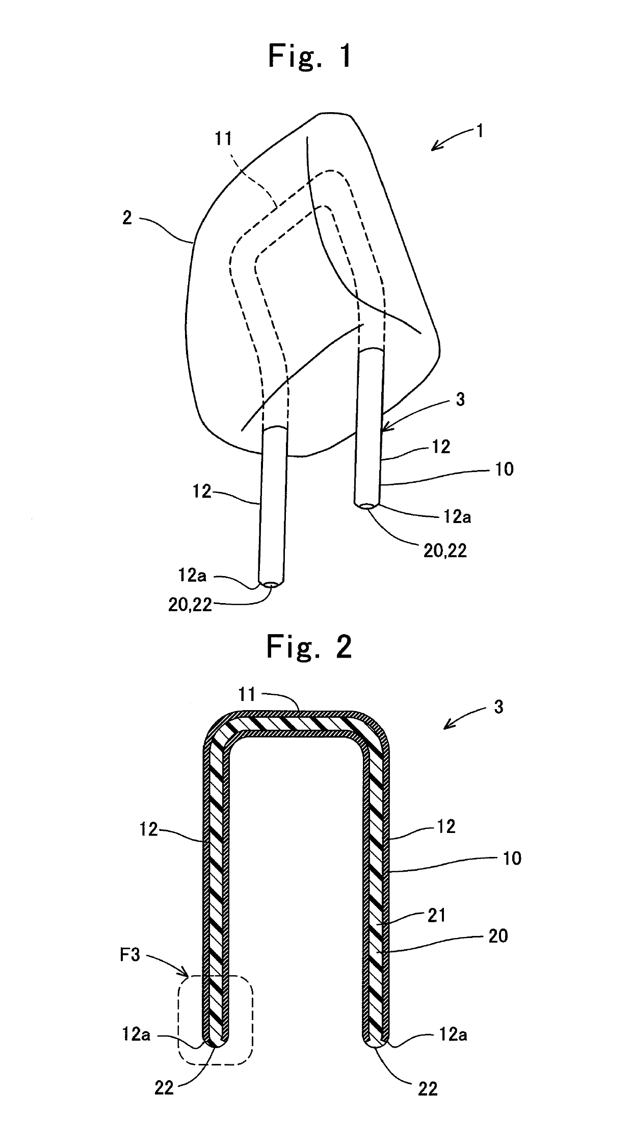
[0021]Explanations will be hereinafter made on the construction of a headrest 1 with reference to FIG. 1. The headrest 1 is installed to a vehicular seat back (not shown) at the upper end detachably in a sticking manner. The headrest 1 comprises a pillow 2 including a cushioning material therein, and a stay 3 (i.e., a stay for headrest) serving as a supporter member.

[0022]The stay 3 is formed as a letter-“U” shape. The stay 3 comprises paired legs that are stuck into the seat back at the upper end. The pillow 2 exposes the paired legs among the stay 3 on the leading end side, and is installed integrally around the other sites in the stay 3.

1-2 Construction of Stay 3

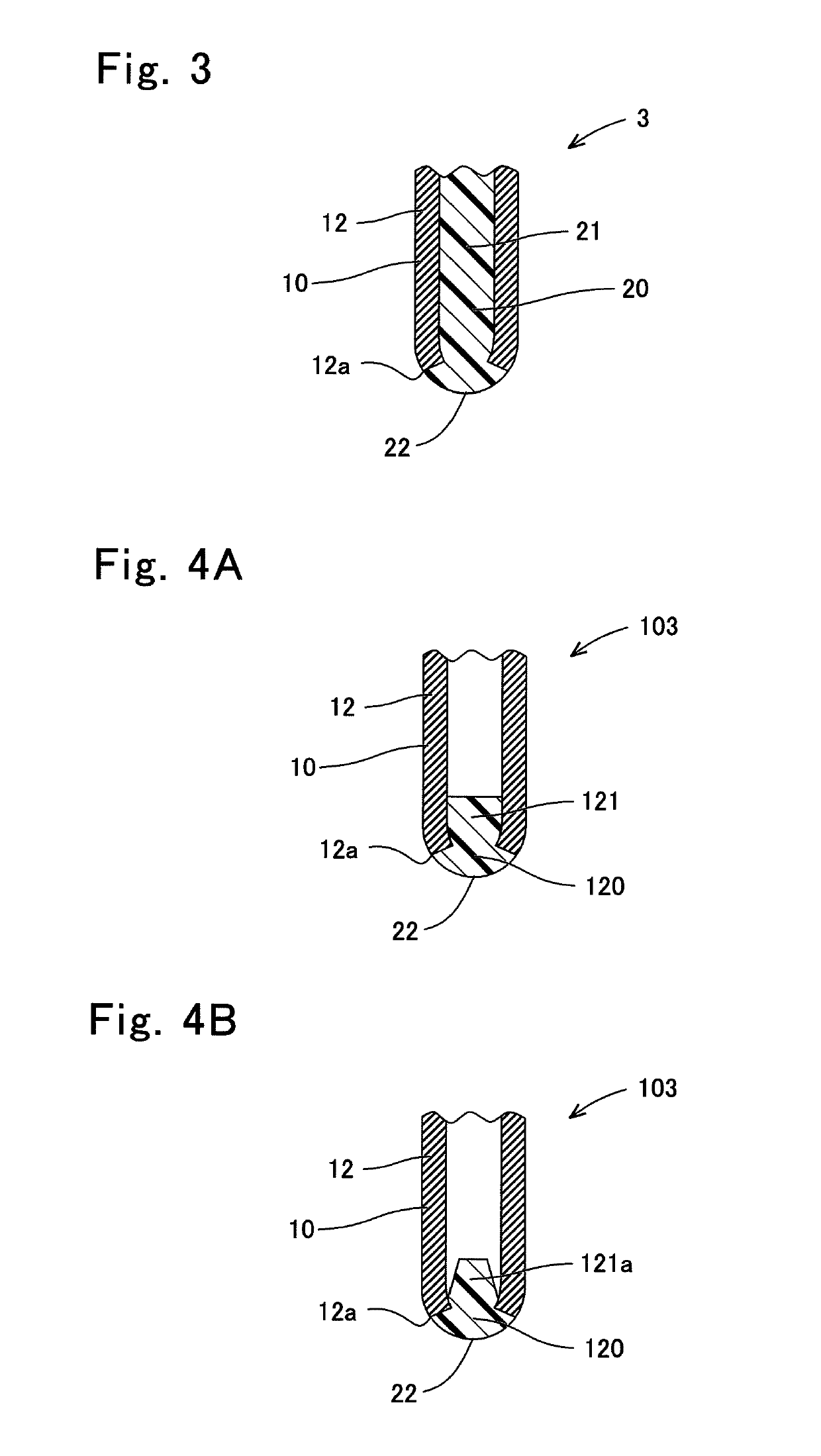
[0023]Explanations will be hereinafter made on a detailed construction of the stay 3 with reference to FIGS. 2 and 3. The stay 3 comprises a hollow metallic stay body 10, and an end installation body 20 arranged integrally into the stay body 10.

[0024]The stay body 10 is formed in a letter-“U”-...

modified embodiment of first embodiment

[0038]Explanations will be hereinafter made on a stay 103 in a modified embodiment of First Embodiment with reference to FIG. 4A. Note that, in this stay 103, identical symbols are put as to the constituents that are identical with those of the stay 3 according to First Embodiment. As illustrated in FIG. 4A, the stay 103 comprises the stay 10, and an end installation body 120. The end installation body 120 includes a solid portion 121, and the spherical portion 22. The solid portion 121 is arranged only in some of the leg 12 partially. Moreover, the solid portion 121 is formed in a diameter that is larger than that of the opening in the leading end 12a. In addition, the end installation body 120 is formed as a constricted shape at the boundary between the solid portion 121 and the spherical portion 22 over the entire circumference.

[0039]Note herein that the end installation portion 120 is formed as a separate-body member that is independent of the stay body 10. The end installation ...

second embodiment

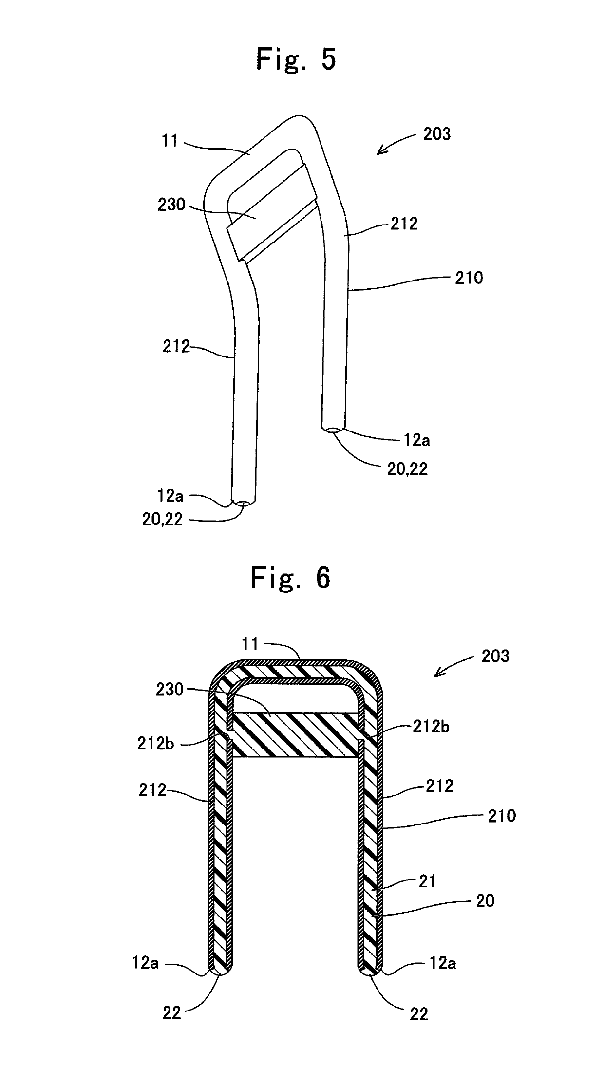
[0044]Explanations will be hereinafter made on a stay 203 according to Second Embodiment with reference to FIGS. 5 and 6. Note that, in this stay 203, identical symbols are put as to the constituents that are identical with those of the stay 3 according to First Embodiment. As illustrated in FIGS. 5 and 6, the stay 203 comprises a stay body 210, the end installation body 20, and an outer installation body 230 serving as a connector member.

[0045]The stay body 210 includes the base 11, and paired legs (212, 212). In addition to the legs (12, 12) in First Embodiment, the legs (212, 212) further include holes or bores (212b, 212b) that are disposed at a site on a side of the base 11, and which are formed to penetrate the stay body 210 from the outer face to the inner face. The bores (212b, 212b) are formed respectively in one of the legs (212, 212) on the side that faces another one of the legs (212, 212). That is, the bore 212b in one of the legs (212, 212), and the bore 212b in the ot...


PUM


Abstract

A stay for headrest includes a hollow metallic stay body, and an end installation body. The stay body is formed as a letter-“U” shape including a base, and paired legs extending respectively from opposite ends of the base. The end installation body is formed of a polymeric material, and includes a solid portion arranged inside a hollow interior in a leading end portion of the paired legs, and a spherical portion protruding from the leading end portion of the paired legs.

Description

CROSS REFERENCE TO RELATED APPLICATIONS[0001]The present application is a Continuation Application of International Application No. PCT / JP2016 / 079038, filed on Sep. 30, 2016, which is incorporated herein by reference. The present invention is based on Japanese Patent Application No. 2015-193160, filed on Sep. 30, 2015, the entire contents of which are incorporated herein by reference.BACKGROUND OF THE INVENTION[0002]1. Field of the Invention[0003]The present invention relates to a stay for headrest.[0004]2. Description of the Related Art[0005]Japanese Unexamined Patent Publication (KOKAI) Gazette No. 2001-327359 (JP2001-327359A) sets forth a stay for headrest, the stay comprising: a hollow stay body; and a foamed resin filled in the hollow interior in the stay body. Japanese Patent Gazette No. 5612989 (JP5612989B2) sets forth that a stay body is formed by metal, and that the stay body is processed at the leading end as a spherical shape.SUMMARY OF THE INVENTION[0006]Incidentally, a ...

Claims


Application Information

Patent Timeline
Patent Type & Authority Patents(United States)
IPC IPC(8): B60N2/80A47C7/38B60N2/894
CPCA47C7/38B60N2/80B60N2/894B60N2/809
Inventor OKUMURA, TAKEMASA
Owner TOKAI CHEM IND CO LTD
Why Eureka
Try Eureka