Interchangeable cylinder lock core for a cylinder lock unit
a technology of cylinder lock and cylinder lock core, which is applied in the direction of cylinder locks, keys, locks, etc., can solve the problem of not having a really high security interchangeable lock cylinder core on the market, and achieve the effect of increasing security
- Summary
- Abstract
- Description
- Claims
- Application Information
AI Technical Summary
Benefits of technology
Problems solved by technology
Method used
Image
Examples
first embodiment
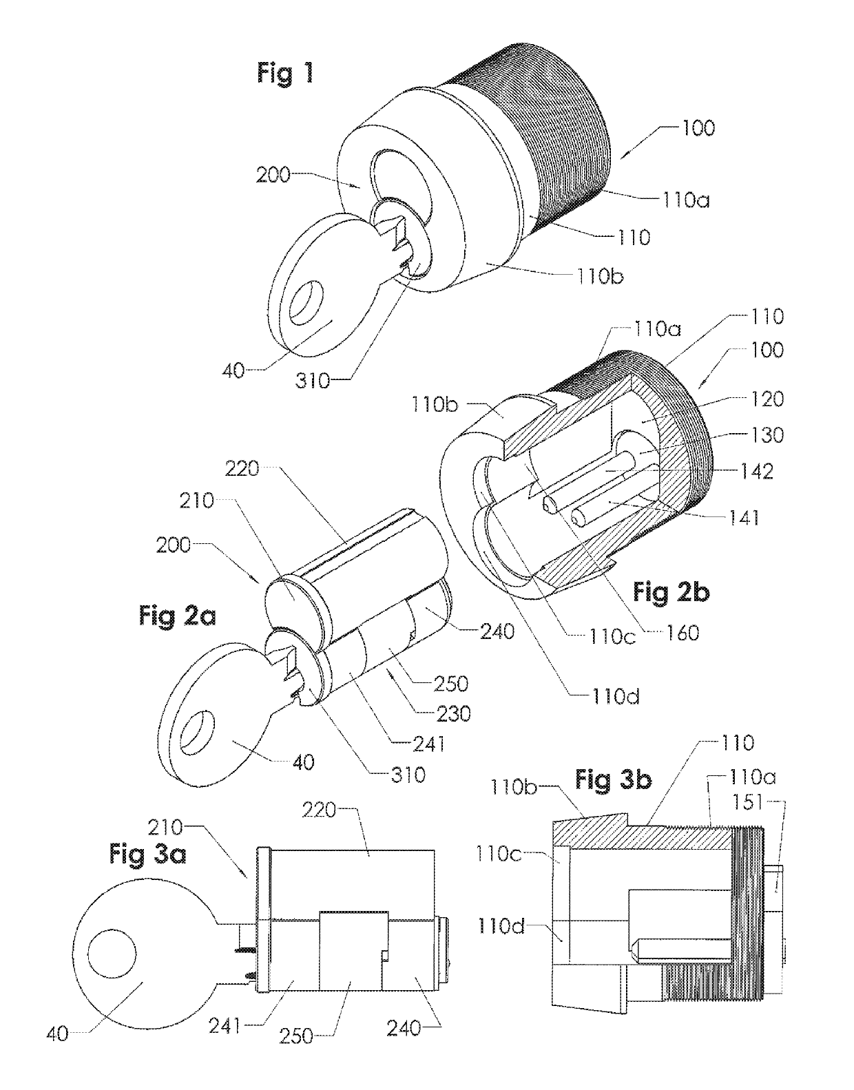
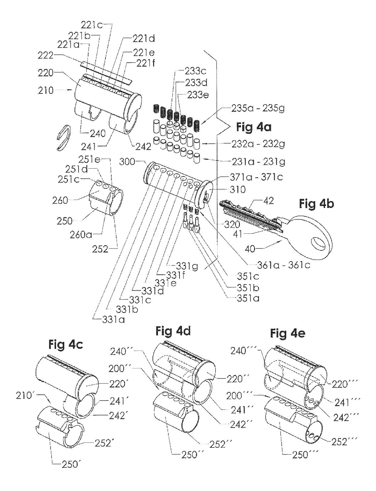
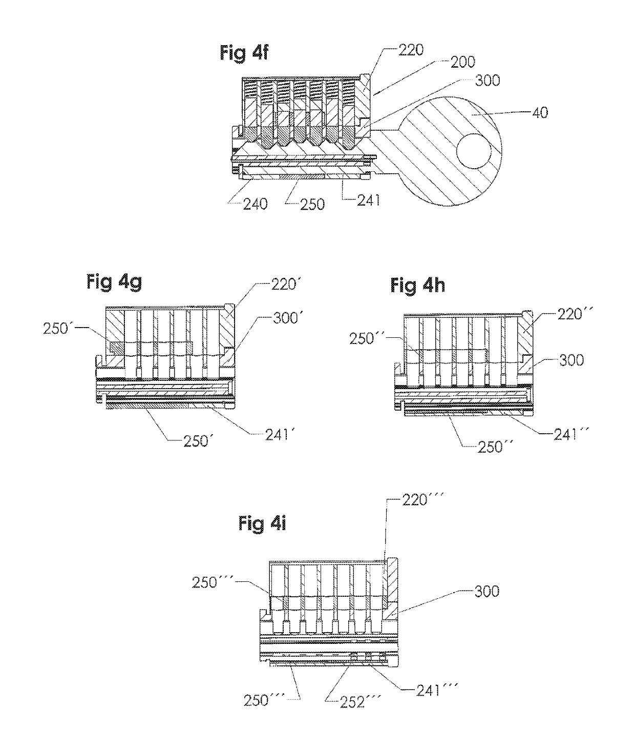
[0067]the invention is shown in FIGS. 1, 2a, 2b, 3a, 3b, 4a, 4b, 4f, 5a, 5b, 5c, 5d and 5e, including a lock unit 100 and an interchangeable cylinder lock core 200 with a rotatable key plug 300 (FIG. 4a).
[0068]The lock unit 100 comprises a cylindrical housing 110 having a threaded rear end portion 110a and a slightly conical front end portion 110b. In a circular hole (not shown specifically) in a rear end wall 120, there is journaled a rotatable plate 130 provided with two parallel rods or prongs 141, 142, which extend in a direction towards the front end portion at the inside of the cylindrical housing 110, and a cam 151 (see FIG. 3b) at the back side of the rear end wall 120. The prongs 141, 142 are coupled to the cam 151 via the plate 130, so that a torque can be transferred from the prongs to e.g. a door lock mechanism.
[0069]The lock unit 100 is normally permanently mounted in a door or the like in order to cooperate with a door locking mechanism, as is well known per se. The fr...
second embodiment
[0088]The back end L2 of the key plug 400 is somewhat longer in this second embodiment, and the front end FR2 is shorter (the total length L2+FR2 being the same as in FIG. 5d).
[0089]In a modified version of the second embodiment, shown in FIGS. 8a, 8b, 8c and 8d, the structure is exactly the same as in the one shown in FIG. 7a, etc., except that the number of central locking pins 231a′, . . . 231f (FIG. 8c) in the key plug 400 is six rather than seven and the total length of the key plug is a little shorter. Still, the length L2′ of the prong holes is slightly more than half of the length of the key plug.
third embodiment
[0090]In a third embodiment, shown in FIGS. 9, 9a, 9b, 9c, 9d, 9e, 9f, 9g, 9h and FIG. 10, the number of central locking pins is again seven, like in most of the previous embodiments, but the side locking mechanism is different, with only two side locking tumblers, on one side of the key plug 500 only, these two side locking tumblers 551a, 551b cooperating with a relatively short side bar 580 (FIG. 9d). Such a side locking mechanism with a side bar is known per se, but not in the context of interchangeable cylinder lock cores having two relatively long prong holes. The side bar 580 is normally held in a longitudinal recess or groove 243 (see FIG. 9a) by a spring 581 (see FIG. 9d), located between the two side locking tumblers to save longitudinal space, in a position where it projects sideways outside the contour of the key plug 500. In this position, the side bar will register with the corresponding groove 243 in the front end sleeve portion 241 of the shell 200 and thereby effecti...
PUM
 Abstract
Description
Claims
Application Information
 - R&D
- Intellectual Property
- Life Sciences
- Materials
- Tech Scout
- Unparalleled Data Quality
- Higher Quality Content
- 60% Fewer Hallucinations
Browse by: Latest US Patents, China's latest patents, Technical Efficacy Thesaurus, Application Domain, Technology Topic, Popular Technical Reports.
© 2025 PatSnap. All rights reserved.Legal|Privacy policy|Modern Slavery Act Transparency Statement|Sitemap|About US| Contact US: help@patsnap.com


