Supercharge Your Innovation With Domain-Expert AI Agents!

Simplified time domain switched ring/disk resonant gyroscope

a time domain switched ring and resonant gyroscope technology, applied in the direction of speed measurement using gyroscopic effects, instruments, surveying and navigation, etc., can solve the problems of low cost and low performance, and achieve the effect of simplifying and improving the design of tdsrrg

Active Publication Date: 2019-07-09
THE UNITED STATES OF AMERICA AS REPRESENTED BY THE SECRETARY OF THE NAVY
View PDF13 Cites 0 Cited by
  • Summary
  • Abstract
  • Description
  • Claims
  • Application Information

AI Technical Summary

Benefits of technology

The present invention provides a system to simplify and improve the design of a TDSRRG. It includes a gyroscope with a support frame, a circular oscillator, a flexible support structure, a drive mechanism, movable sections, and digital proximity switches. The drive mechanism induces the circular oscillator into a two-dimensional driving oscillation. The system identifies the position of each movable section and determines the plurality of variable oscillation parameters for each oscillation of the modified drive oscillation. This allows for the determination of the angular rotation of the support frame and the circular oscillator. Overall, the system simplifies the design of the TDSRRG and improves its performance.

Problems solved by technology

For such sensors, there is generally a strong correlation between cost, size, weight, power, and performance; specifically, low cost, size, weight, and power generally implies low performance.

Method used


Image

  • Simplified time domain switched ring/disk resonant gyroscope
  • Simplified time domain switched ring/disk resonant gyroscope
  • Simplified time domain switched ring/disk resonant gyroscope

Examples


Embodiment Construction

[0015]The present invention provides a system for simplifying and improving the design of a TDSRRG.

[0016]Gyroscopes are sensors that are used to detect presence of rotation or rate of rotation. For these technologies, in general there is a strong correlation between cost, size, weight, power, and performance; specifically, low cost, size, weight, and power (CSWaP) generally imply low performance.

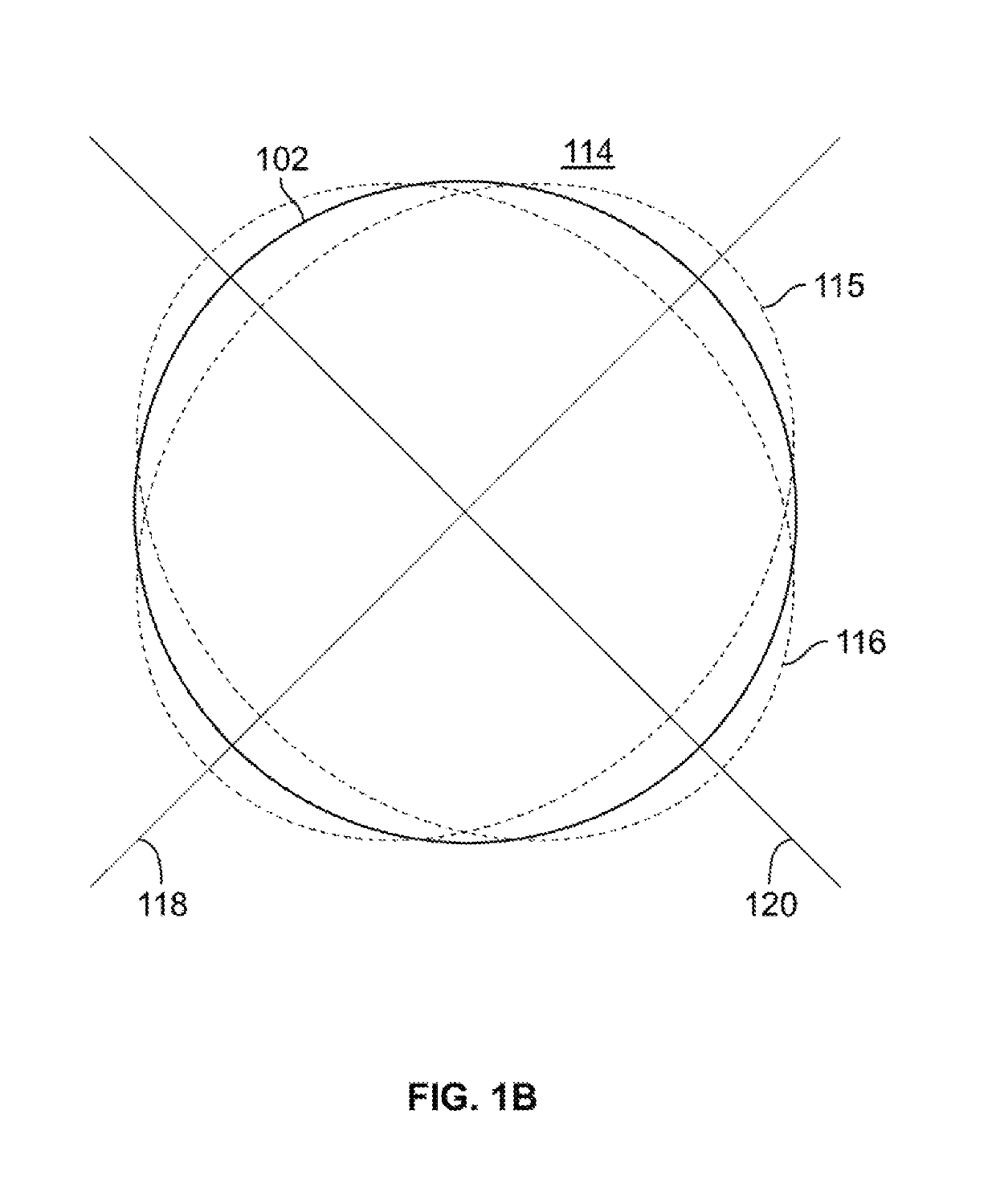
[0017]A common type of gyroscope is a microelectromechanical systems (MEMS) gyroscope. Prior art MEMS gyroscopes provide low CSWaP but usually achieve only consumer- or tactical-grade performance. Various types of MEMS gyroscopes exist, but the majority sense rotation via the Coriolis force. A CVG employs a proof mass that is driven into an oscillatory mode; this proof mass is usually a symmetric structure, such as a ring or disk, with several vibratory modes. A CVG senses rotation through energy transferred from one vibratory mode to another vibratory mode due to the Coriolis force that the...


PUM


Abstract

A gyroscope includes: a support frame; a circular oscillator; a flexible support structure supporting by suspension the circular oscillator to the support frame; a drive mechanism configured to induce the circular oscillator into a two-dimensional driving oscillation; a plurality of movable sections disposed at a perimeter of the circular oscillator; a plurality of digital proximity switches, each disposed near a respective movable section and around the perimeter of the circular oscillator; and a processor. The two-dimensional driving oscillation is modified responsive to an angular rotation of the support frame and the circular oscillator. The processor is operable to determine the position of each movable section, to determine the plurality of variable oscillation parameters for each oscillation of the modified drive oscillation and to determine the angular rotation of the support frame and the circular oscillator via a parametric system identification method.

Description

FEDERALLY-SPONSORED RESEARCH AND DEVELOPMENT[0001]The United States Government has ownership rights in this invention. Licensing inquiries may be directed to Office of Research and Technical Applications, Space and Naval Warfare Systems Center, Pacific, Code 72120, San Diego, Calif., 92152; telephone (619) 553-5118; email: ssc_pac_t2@navy.mil. Reference Navy Case No. 104,111.BACKGROUND OF THE INVENTION[0002]Embodiments of the invention relate to improvements and simplifications in the design of a time domain switched ring / disk resonant gyroscope (TDSRRG).[0003]Gyroscopes are types of sensors used to detect rotation or rotation rate. For such sensors, there is generally a strong correlation between cost, size, weight, power, and performance; specifically, low cost, size, weight, and power generally implies low performance.[0004]There exists a need for a system to lower costs and improve performance of gyroscopes.SUMMARY OF THE INVENTION[0005]An aspect of the present invention is draw...

Claims


Application Information

Patent Timeline
Patent Type & Authority Patents(United States)
IPC IPC(8): G01C19/5726G01C19/5755G01C19/5684
CPCG01C19/5755G01C19/5726G01C19/5684
Inventor SABATER, ANDREW B.
Owner THE UNITED STATES OF AMERICA AS REPRESENTED BY THE SECRETARY OF THE NAVY
Features
  • R&D
  • Intellectual Property
  • Life Sciences
  • Materials
  • Tech Scout
  • Unparalleled Data Quality
  • Higher Quality Content
  • 60% Fewer Hallucinations
Learn More