Molded foam member manufacturing method and shock absorbing member

a technology of molded foam and manufacturing method, which is applied in the direction of domestic applications, other domestic articles, domestic articles, etc., can solve the problems of positional displacement between, and achieve the effect of suppressing the positional displacement of rigid plates and good precision

Active Publication Date: 2019-07-16
ARCHEM INC
View PDF19 Cites 2 Cited by
  • Summary
  • Abstract
  • Description
  • Claims
  • Application Information

AI Technical Summary

Benefits of technology

[0022]Due to the above configuration, the present invention is capable of suppressing positional displacement of a rigid plate due to foaming pressure, and also capable of molding a molded foam member with good precision at both faces of the rigid plate.

Problems solved by technology

However, during molding of the molded foam member, there is a concern of the iron plate being lifted up by foaming pressure of a foaming agent, and of positional displacement arising between the molded foam member and the iron plate inside the mold.

Method used


Image

  • Molded foam member manufacturing method and shock absorbing member
  • Molded foam member manufacturing method and shock absorbing member
  • Molded foam member manufacturing method and shock absorbing member

Examples


Embodiment Construction

[0033]Explanation follows regarding the structure of a manufacturing method of a molded foam member according to an exemplary embodiment, with reference to the drawings.

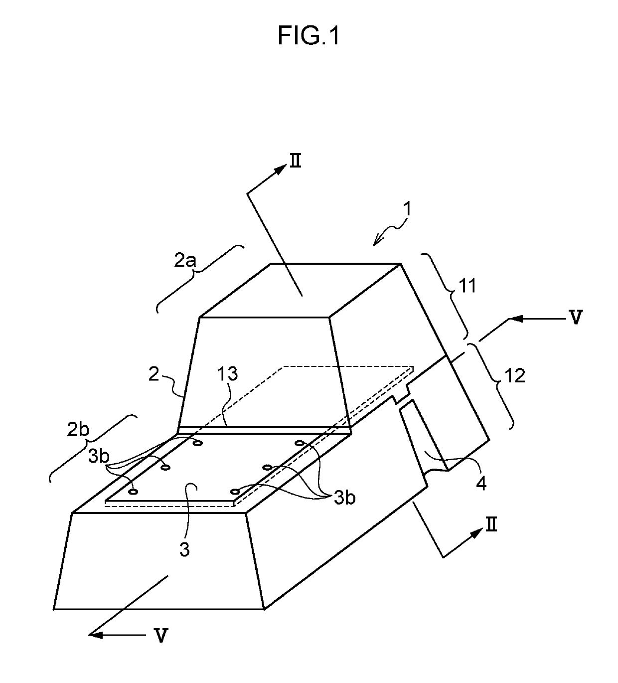
[0034]Explanation follows regarding an exemplary embodiment, with reference to the drawings. Note that in the following exemplary embodiment, explanation is given regarding an example in which a shock absorbing member (abbreviated below to “EA member”) attached to the inside an automobile door is employed as the molded foam member. However, the present invention is also applicable to other molded foam members and their manufacturing methods.

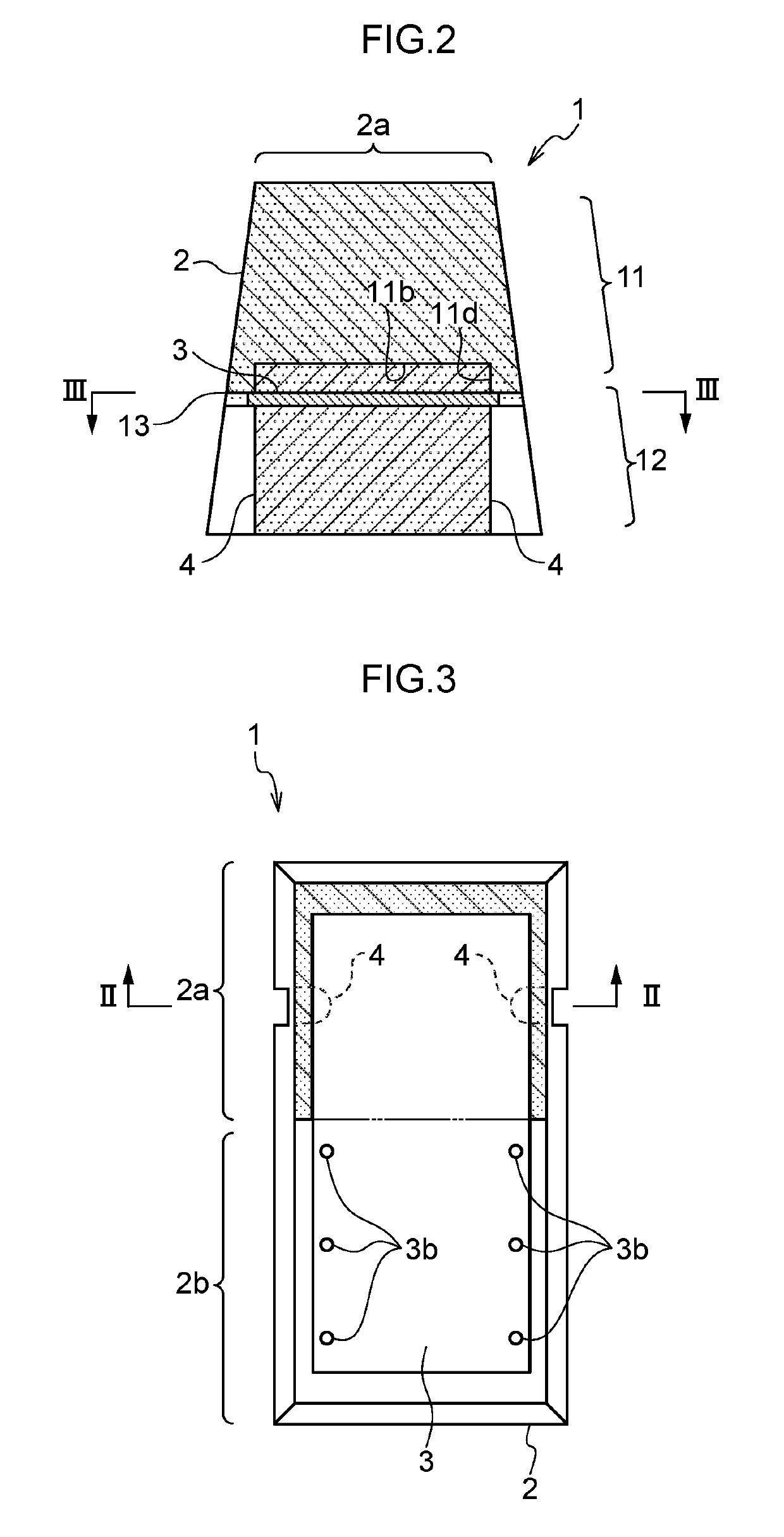
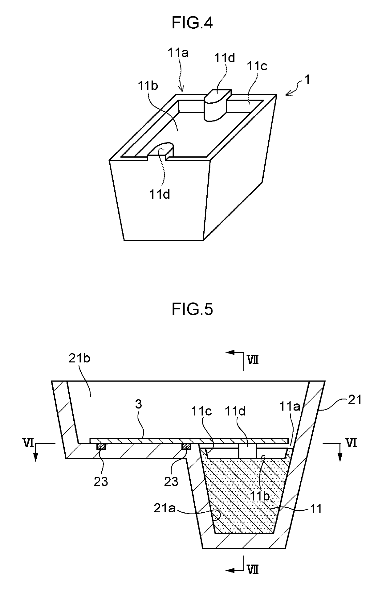
[0035]FIG. 1 is a perspective view illustrating an EA member 1 (shock absorbing member) serving as a molded foam member according to an exemplary embodiment. FIG. 2 and FIG. 3 are respective cross-sections of the EA member. Note that FIG. 2 is a cross-section taken along lines II-II in FIG. 1 and FIG. 3, and FIG. 3 is a cross-section taken along line III-III in FIG. 2. FIG. 4 is a...


PUM

PropertyMeasurementUnit
diameteraaaaaaaaaa
diameteraaaaaaaaaa
thicknessaaaaaaaaaa

Abstract

A molded foam member manufacturing method including: a first process of placing a foam molded first portion and a rigid member in a second portion forming mold, and pressing and fixing the rigid member against the second portion forming mold; and a second process of pouring a second portion-forming synthetic resin raw material into the second portion forming mold and foam molding a second portion so as to surround at least a portion of the rigid member and to form an integral unit with the first portion.

Description

CROSS REFERENCE TO RELATED APPLICATIONS[0001]This application is a National Stage of International Application No. PCT / JP2014 / 069759 filed Jul. 25, 2014, claiming priority based on Japanese Patent Application No. 2013-159774, filed Jul. 31, 2013, the contents of all of which are incorporated herein by reference in their entirety.TECHNICAL FIELD[0002]The present invention relates to a manufacturing method for a molded foam member and a shock absorbing member.BACKGROUND ART[0003]Shock absorbing members formed from molded foam members such as hard polyurethane foams are attached to automobile doors in order to absorb impact energy in the event of a side-on collision.[0004]Structures have been proposed for improving shock absorption performance by providing a rigid member with higher rigidity than a molded foam member at an impact receiving face of the molded foam member. For example, shock absorbing members exist that have a structure in which a molded foam member is affixed to one fac...

Claims


Application Information

Patent Timeline
Patent Type & Authority Patents(United States)
IPC IPC(8): B29C44/12B29C44/40B29C39/10B29K105/04B29L31/30
CPCB29C44/1233B29C44/1271B29C44/1285B29C44/40B29L2031/3005B29C39/10B29K2105/04B29L2031/30
Inventor NABESHIMA, YOICHISATO, MASATOSHITAKAHASHI, YOSHIYUKI
Owner ARCHEM INC
Why Eureka
Try Eureka