
Transfer mold body

a mold body and transfer technology, applied in the field of transfer mold bodies, can solve the problems of printing letters that may sometimes displace from the set position, incur an increase in the cost of the body to be transferred, etc., and achieve the effect of suppressing the increase in cost and suppressing the displacement of position

Inactive Publication Date: 2014-05-13
KK TOKAI RIKA DENKI SEISAKUSHO
View PDF1 Cites 1 Cited by
  • Summary
  • Abstract
  • Description
  • Claims
  • Application Information

AI Technical Summary

Benefits of technology

The present invention is to provide a transfer mold body that can show lettering or the like without increasing cost, and without causing positional displacement. The transfer mold body can be manufactured at low cost since the first and second mold portions are integrally molded by two-color molding. This helps to suppress an increase in cost and allows for the display of lettering or the like without requiring significant modification. The transfer mold body can also be designed to further suppress an increase in cost.

Problems solved by technology

However, when printing lettering or the like on the body to be transferred by using for example pad printing, the printed letter may sometimes displace from the set position of the letter on the body to be transferred.
Moreover, a process for printing lettering or the like on the body to be transferred is a post-process subsequent to transferring the transfer layer onto the body to be transferred, with the issue that incurs an increase in costs of the body to be transferred.

Method used


Image

  • Transfer mold body
  • Transfer mold body
  • Transfer mold body

Examples


Embodiment Construction

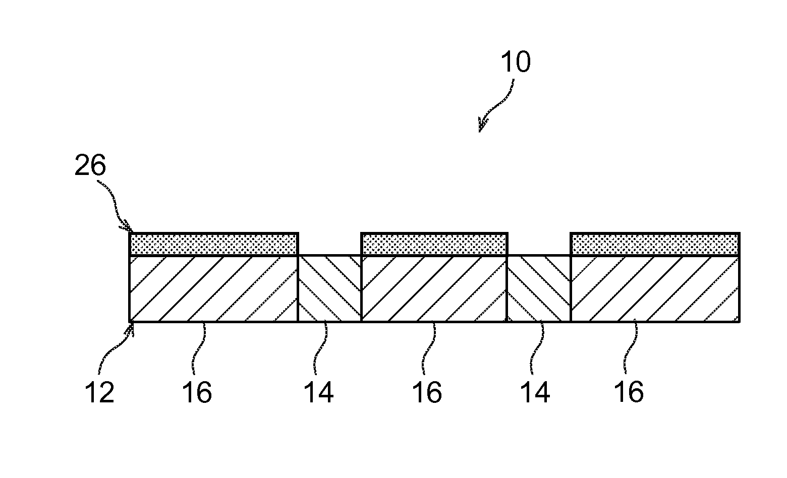
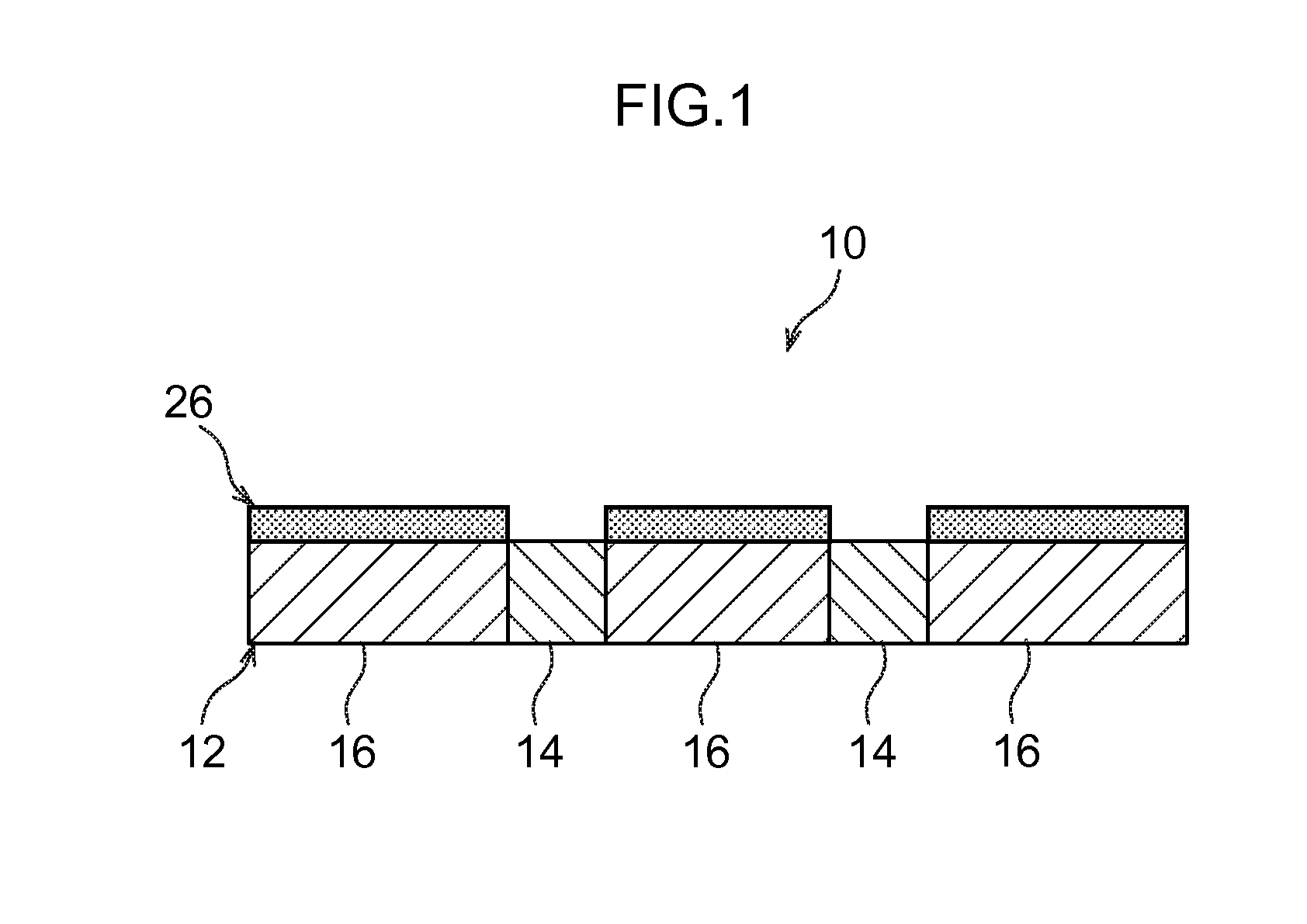
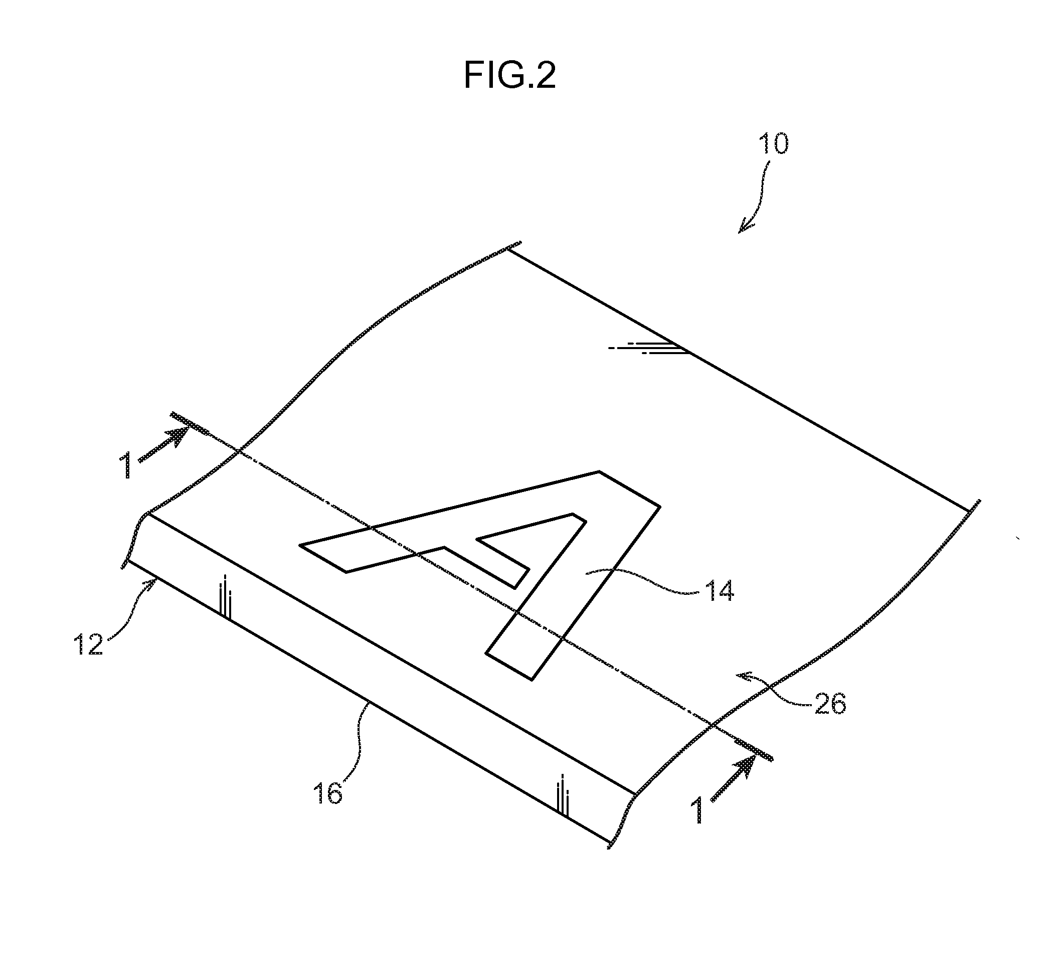
[0034]Explanation first follows regarding a transfer mold body 10 according to an exemplary embodiment of the present invention, followed by explanation regarding a transfer apparatus 30 for manufacturing the transfer mold body 10.

[0035]Regarding the Transfer Mold body 10

[0036]FIG. 1 is an enlarged cross-section illustrating a portion of the transfer mold body 10. FIG. 2 is a cut-away perspective view illustrating a portion of the transfer mold body 10. The transfer mold body 10 is for example applied to an interior member of a vehicle (such as a design panel affixed to an instrument panel, a grille of an vehicle mounted navigation device or a vehicle mounted audio device, a panel of a vehicle installed heater controller, or a panel assembled to a vehicle shift lever case).

[0037]The transfer mold body 10 is configured including a base member 12 and a transfer layer 26. The base member 12 is configured including a display portion 14 serving as a “first mold portion” and a main body p...


PUM

PropertyMeasurementUnit
adhesive propertiesaaaaaaaaaa
shapeaaaaaaaaaa
pressureaaaaaaaaaa

Abstract

In a transfer mold body, a display portion is formed from a crystalline resin and a main body portion is formed from an amorphous resin. Accordingly, a transfer layer is only transferred to the amorphous resin formed main body portion that has good transfer properties for the transfer layer, and the transfer layer is not transferred to the crystalline resin formed display portion that has poor transfer properties for the transfer layer. Accordingly, only the main body portion is decorated by the transfer layer, with the display portion to which the transfer layer is not transferred visibly displayed as the letter. Accordingly, since printing process is not necessary, suppressing an increase in cost of the transfer mold body. Moreover, the position of the letter is determined by two-color molding of the main body portion and the display portion, enabling positional displacement of the letter to be suppressed.

Description

CROSS-REFERENCE TO RELATED APPLICATION[0001]This application claims priority under 35 USC 119 from Japanese Patent Application No. 2012-099958 filed Apr. 25, 2012, the disclosure of which is incorporated by reference herein.BACKGROUND OF THE INVENTION[0002]1. Field of the Invention[0003]The present invention relates to a transfer mold body that includes a transfer layer.[0004]2. Related Art[0005]Japanese Patent Application Laid-Open (JP-A) No. 06-15945 discloses a transfer method in which a transfer layer is transferred to a boy to be transferred (transfer mold body). More specifically, a transfer member including a transfer layer and a base film is disposed facing the body to be transferred, and the base film is separated from the transfer layer after applying heat and pressure to the transfer member, thereby transferring the transfer layer to the body to be transferred.[0006]In a case of displaying lettering or the like on such body to be transferred, the lettering or the like is ...

Claims


Application Information

Patent Timeline
Patent Type & Authority Patents(United States)
IPC IPC(8): B32B3/10
CPCB41F16/0006B29C45/02B41M5/382B41F19/08B44C5/0453B44C1/1712B32B3/10Y10T428/24802
Inventor SUGISAKA, KENICHIICHIKAWA, TAKASHIYAMADA, EIJITSUKIHARA, ATSUSHISADAMATSU, RYUSUKEIMAEDA, KATSUYUKIOGAWA, SOICHIRO
Owner KK TOKAI RIKA DENKI SEISAKUSHO
Learn More