Display device and television set

a technology for a display device and a television set, which is applied in the direction of television systems, lighting and heating apparatus, instruments, etc., can solve the problems of insufficient modification of the separation (positional displacement) of the circuit board from the lower frame, disadvantageous reduction of the quantity of light incident on the light guide plate, etc., to suppress the reduction of the quantity of light incident and suppress the effect of positional displacemen

Inactive Publication Date: 2015-10-13
FUNAI ELECTRIC CO LTD
View PDF10 Cites 0 Cited by
  • Summary
  • Abstract
  • Description
  • Claims
  • Application Information

AI Technical Summary

Benefits of technology

[0009]The present invention has been proposed in order to solve the aforementioned problem, and an object of the present invention is to provide a display device and a television set each capable of suppressing a reduction in the quantity of light incident on a light guide plate by suppressing positional displacement between a light source and a light incident surface of the light guide plate.

Problems solved by technology

In the liquid crystal display device according to Japanese Patent Laying-Open No. 2007-163620, however, the projecting portion of the upper frame simply comes into line contact with the side of the circuit board on the front side after completion of assembling, so that the separation (positional displacement) of the circuit board from the lower frame may be unable to be sufficiently modified.
Therefore, the quantity of light incident on the light guide plate may be disadvantageously reduced by positional displacement between the LED light source and the light incident surface of the light guide plate.

Method used


Image

  • Display device and television set
  • Display device and television set
  • Display device and television set

Examples


Embodiment Construction

[0042]An embodiment of the present invention is hereinafter described with reference to the drawings.

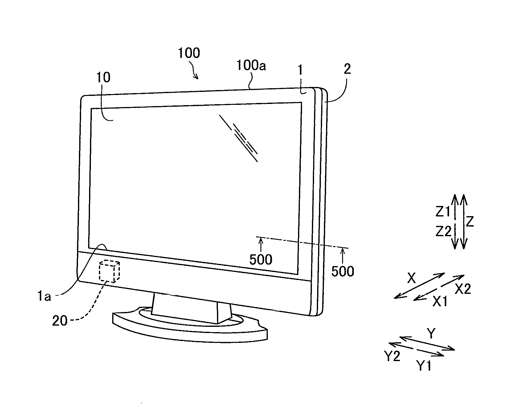
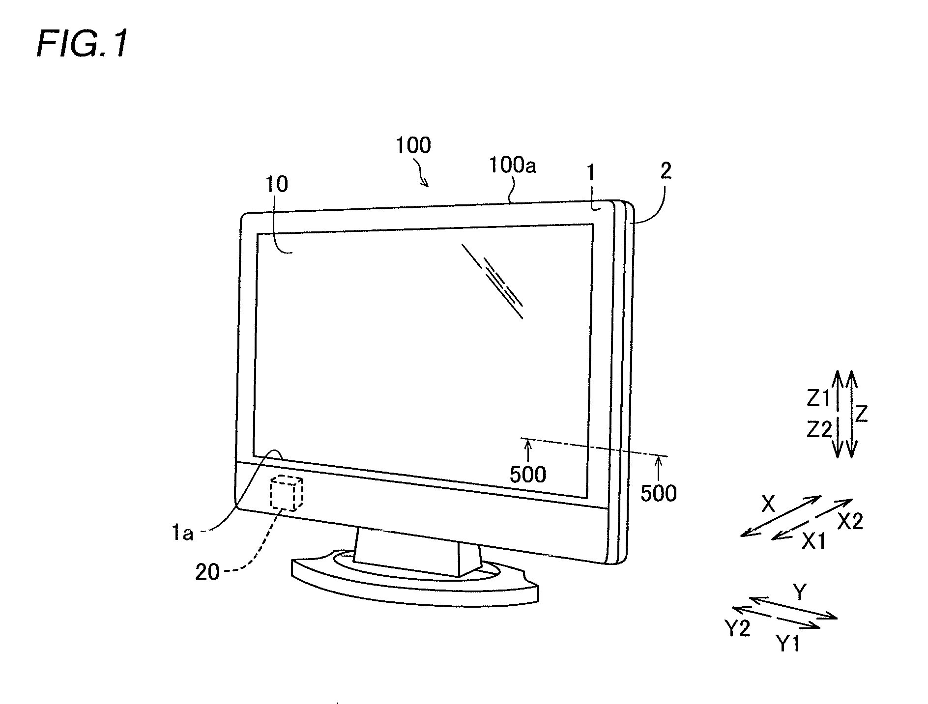
[0043]The structure of a TV (television set) 100 according to the embodiment of the present invention is now described with reference to FIGS. 1 to 6. The TV 100 is an example of the “display device” in the present invention.

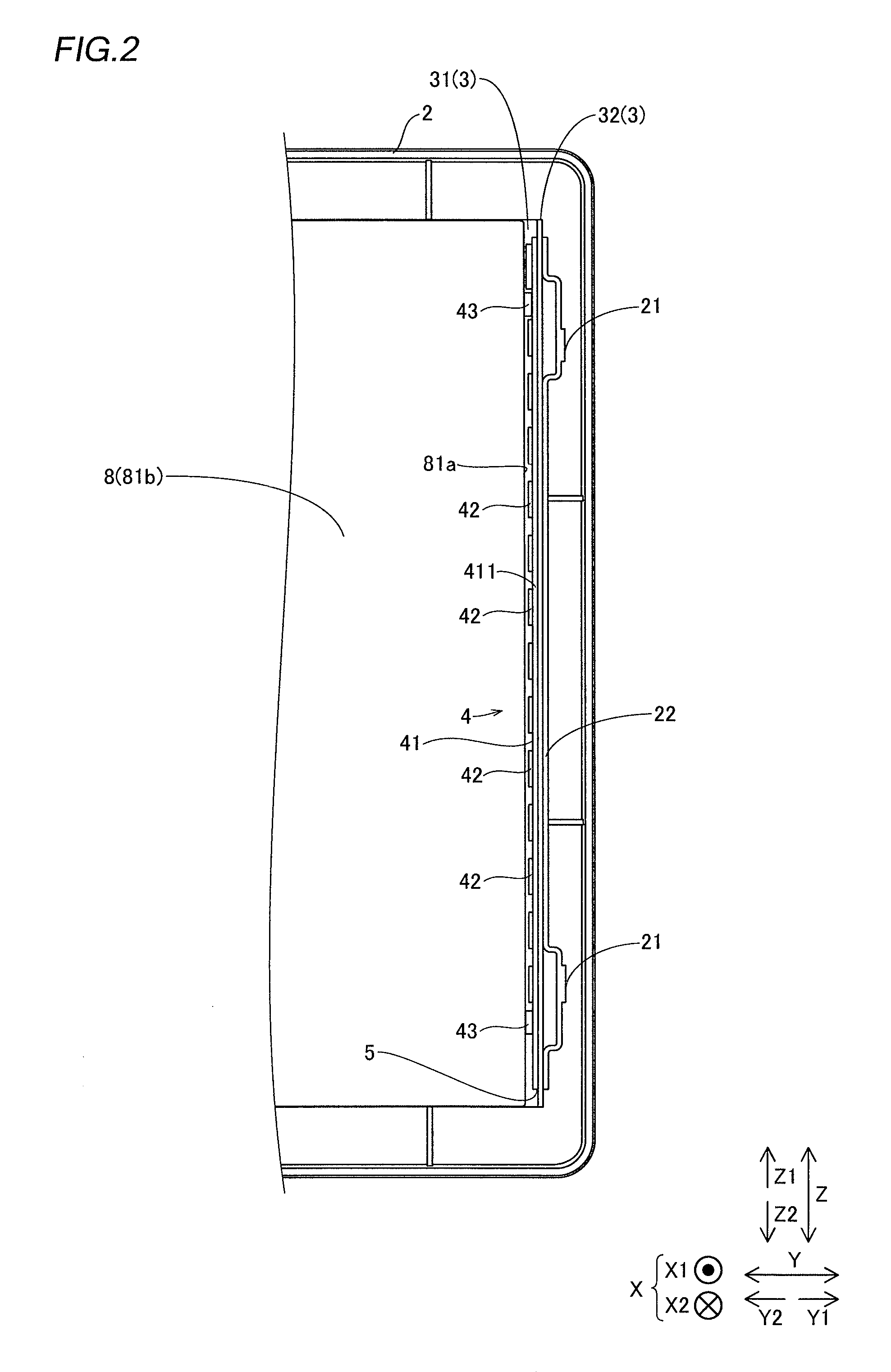
[0044]The TV 100 according to the embodiment of the present invention has a substantially rectangular shape as viewed from the front side (X1 side), as shown in FIG. 1. The TV 100 includes a front frame 1 having an opening 1a and a rear frame 2. The rear frame 2 includes claw portions 21 (see FIG. 3) engaging with holes 91 (see FIG. 3) of a resin frame 9 described later. A display portion 10 displaying an image is exposed from the opening 1a of a TV body 100a (front frame 1). The display portion 10 is mainly constituted by a liquid crystal cell. The TV 100 is configured to be capable of receiving a broadcast signal by a receiving portion 20. The TV body 100a is a...


PUM


Abstract

This display device includes a display device body, a display portion arranged on the front side of the display device body, a light source substrate, a light guide plate arranged on the rear side of the display portion to be opposed to the light source substrate mounted with the light source, having a light incident surface including a side surface receiving light emitted from the light source, a heat sink arranged on the rear side of the light guide plate, including a light source substrate fixing portion to which the light source substrate is attached and fixed by a double-faced adhesive tape, and a substrate pressing portion pressing the front end surface of the light source substrate attached to the light source substrate fixing portion in a direction toward the bottom surface of the heat sink in a surface contact state.

Description

BACKGROUND OF THE INVENTION[0001]1. Field of the Invention[0002]The present invention relates to a display device and a television set, and more particularly, it relates to a display device and a television set each including a light source substrate and a light guide plate.[0003]2. Description of the Background Art[0004]A display device including a light source substrate and a light guide plate is known in general, as disclosed in Japanese Patent Laying-Open No. 2007-163620.[0005]Japanese Patent Laying-Open No. 2007-163620 discloses a liquid crystal display device (display device) including a liquid crystal display device body (display device body), a liquid crystal panel (display portion) arranged on the front side of the liquid crystal display device body, displaying an image, and a circuit board (light source substrate) mounted with an LED light source (light source) supplying light to the liquid crystal panel. This liquid crystal display device further includes a light guide pl...

Claims


Application Information

Patent Timeline
Patent Type & Authority Patents(United States)
IPC IPC(8): F21V8/00H04N5/66H04N5/44A47F3/00F21V7/04
CPCG02B6/0085G02B6/0088G02B6/009
Inventor SASAOKA, HIROMASA
Owner FUNAI ELECTRIC CO LTD
Why Eureka
Try Eureka