Aperture device and optical instrument

Inactive Publication Date: 2014-10-09
SEIKO PRECISION INC
View PDF2 Cites 0 Cited by
  • Summary
  • Abstract
  • Description
  • Claims
  • Application Information

AI Technical Summary

Benefits of technology

The invention aims to provide a device and optical instrument that can prevent the movement of a blade in position.

Problems solved by technology

Further, in a case of using a stepping motor as the drive source, a rotor might stop in an unstable position because of the property of this motor.

Method used


Image

  • Aperture device and optical instrument
  • Aperture device and optical instrument
  • Aperture device and optical instrument

Examples


Embodiment Construction

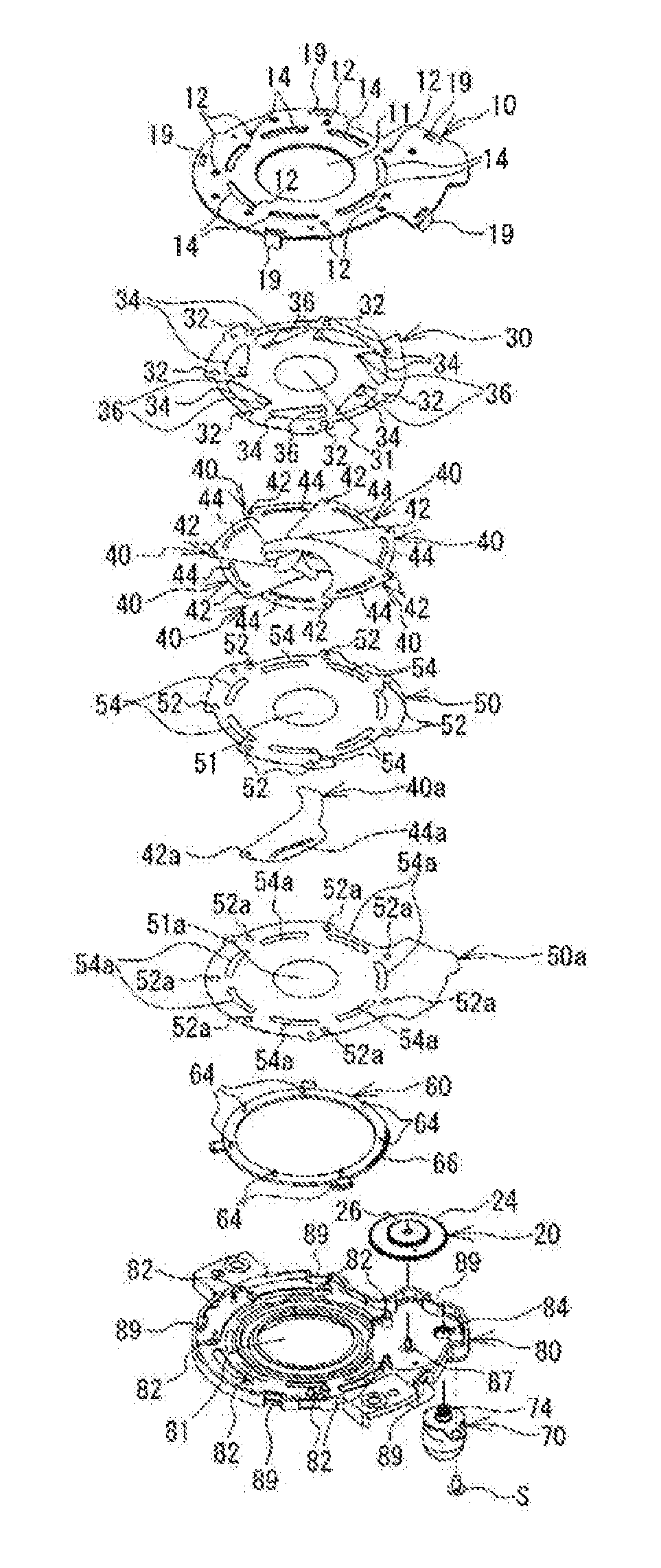
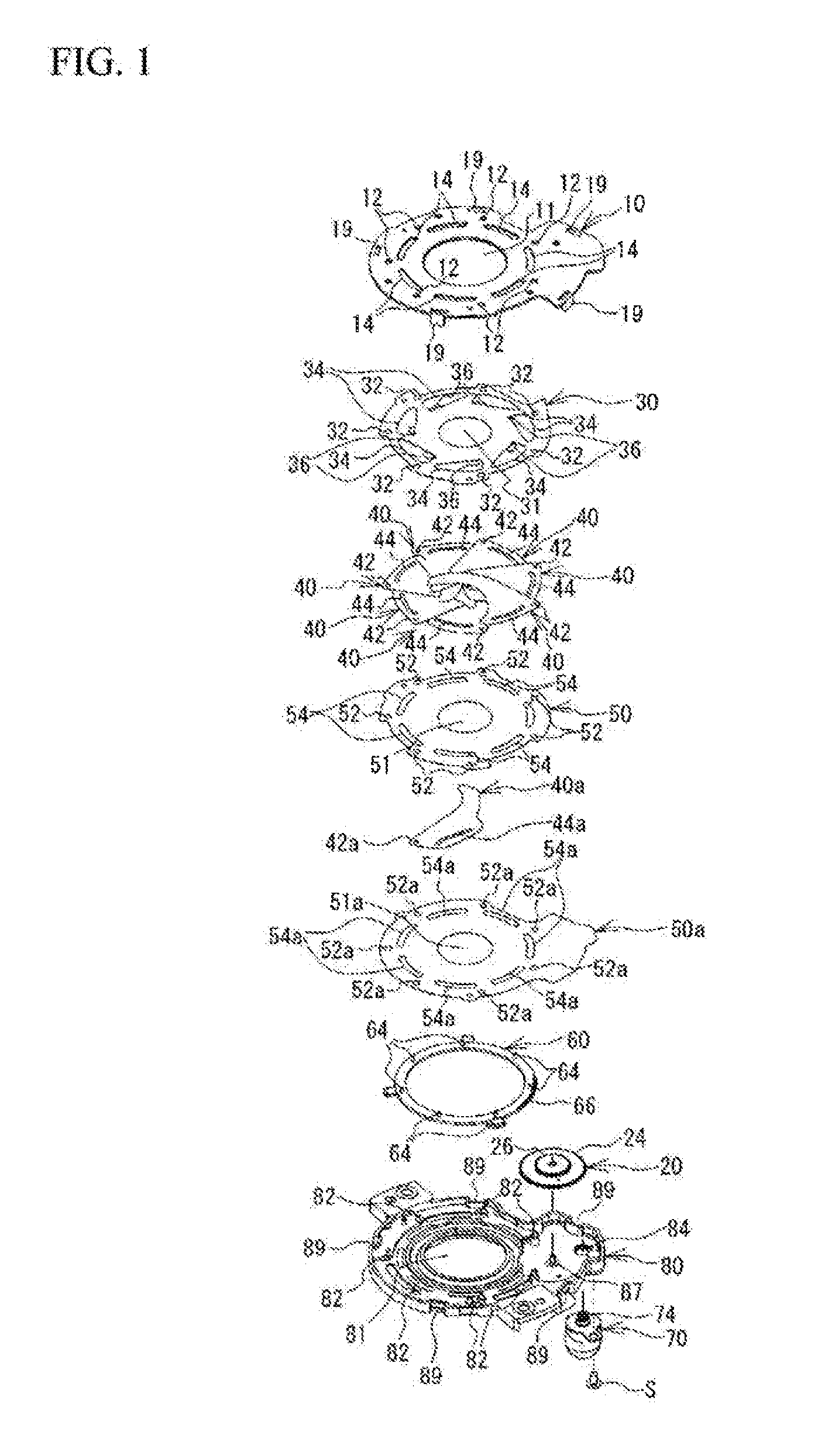
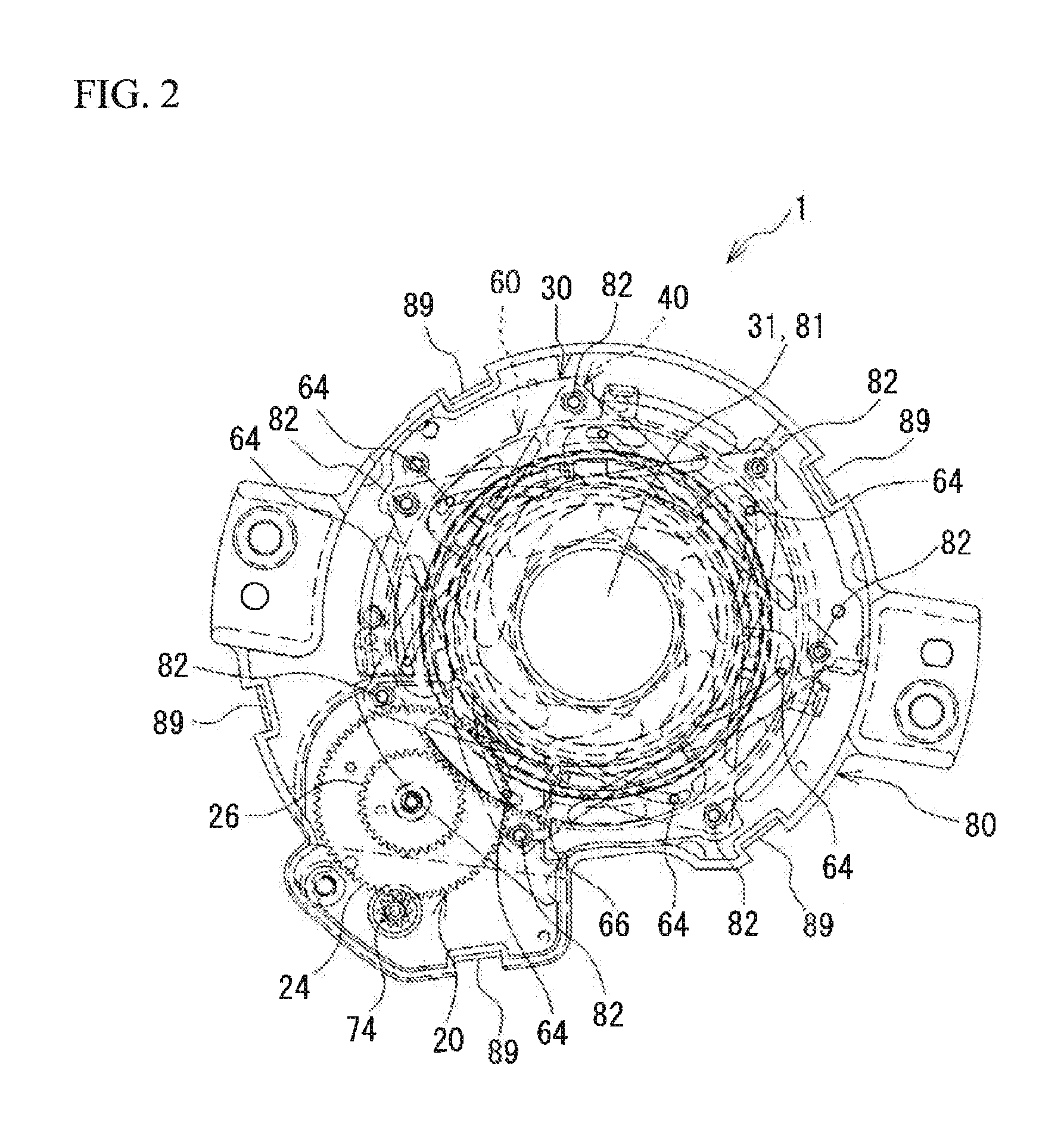
[0014]FIG. 1 is a perspective view of an aperture device 1 according to the present embodiment. The aperture device 1 includes a board 10, a gear 20, a receiving plate 30, plural blades 40, a supporting blade 40a, receiving plates 50 and 50a, a drive ring 60, a. stepping motor 70, and a board 80. The aperture device 1 according to the present embodiment is employed in a camera (optical instrument).

[0015]The gear 20, the receiving plate 30, the blades 40, the supporting blade 40a, the receiving plates 50 and 50a, the drive ring 60, and the stepping motor 70 are housed between the boards 10 and 80. The board 10, the receiving plates 30, 50, and 50a, and the board 80 are respectively formed with openings 11, 31, 51, 51a, and 81, for defining the optical path, at their centers. Additionally, each of the openings 31, 51, and 51a is smaller than each of the openings 11 and 81. The drive force of the stepping motor 70 is transmitted to the plural blades 40 and the supporting blade 40a via ...


PUM


Abstract

An aperture device includes: a board including an opening; a blade opening and closing the opening; and first and second receiving plates sandwiching the blade; wherein the first receiving plate includes a pressing portion partially pressing the blade toward the second plate.

Description

CROSS-REFERENCE TO RELATED APPLICATION[0001]This application is a continuation of and claims priority to International Patent Application No. PCT / JP2013 / 050175 filed on Jan. 9, 2013, which claims priority to Japanese Patent Application No. 2012-099254 filed on Apr. 24, 2012, subject matter of these patent documents is incorporated by reference herein in its entirety.BACKGROUND[0002](i) Technical Field[0003]The present invention relates to aperture devices and optical instruments.[0004](ii) Related Art[0005]Japanese Unexamined Patent Application Publication No. 2009-31663 discloses an aperture device in which a diameter of an opening formed in a board is adjusted by blades.[0006]For example, when the blades stop in respective desired positions, the impact is applied to the aperture device, so the blades might be positionally displaced from the respective desired positions. In particular, when the blades stop in a non-energized state of a motor serving as a drive source for the blades...

Claims


Application Information

Patent Timeline
IPC IPC(8): G02B26/02
CPCG02B26/02G03B9/06G03B9/02G03B9/00G02B9/08G03B9/07G03B9/08
Inventor GOKITA, KATSUHISASHIODA, KAZUYAKUDO, KENICHI
Owner SEIKO PRECISION INC
Why Eureka
Try Eureka