Mounting fixture of a connection fixture

a technology of mounting fixture and connection fixture, which is applied in the direction of rod connection, mechanical apparatus, fastening means, etc., can solve the problems of significant cost of mounting fixture detracting from the desired aesthetic appeal of mounting fixture and associated connection fixture, and the cost of mounting fixture and transpor

Inactive Publication Date: 2019-07-16
MILNER WAYNE RUSSELL +1
View PDF36 Cites 3 Cited by
  • Summary
  • Abstract
  • Description
  • Claims
  • Application Information

AI Technical Summary

Benefits of technology

[0017]The mounting fixture of the present invention therefore connects the cooperating fixture sections together using a connection or connection element which is hidden from view in normal use, i.e. when the mounting sleeve is secured over a tubular member such as a pole. This provides an aesthetically pleasing mounting fixture appearance (for example comparable to single piece mounting fixtures such as shown in WO2009 / 126989A1 and Australian Design Registration No. 328482) as the fastening element is concealed from view when mounted over a tubular member. In some embodiments, this enables the mounting fixture to be configured to have a similar appearance as a unitary and / or integrally moulded mounting fixture. This can provide greater consumer acceptance of the overall connection fixture. Furthermore, the use of an internal connecting arrangement places the connection between the interconnected fixture sections within the mounting sleeve when the mounting fixture is secured over a tubular member, thereby preventing unwanted tampering with that connecting arrangement. In this respect, each connecting arrangement is typically in a location which is only accessible from the inner side of each fixture section when each fixture section is interconnected to form the mounting sleeve.
[0046]The connector can comprise any suitable connector or fastening arrangement which can extend through and connect the first connection section and the second connection section. In one embodiment, the connector comprises a nut and bolt arrangement, the nut including an elongate shaft which extends through the apertures of the first connection section and the second connection section. Where the first connection section and the second connection section comprise a flange, nut of the connector can in some embodiments be mounted to, fixed to, or integrally formed with one of the flanges of the first connection section. In use, this enables easy assembly of the respective receiving element to the mounting element, as the user does not need to manipulate both the bolt and nut.

Problems solved by technology

The moulding and transport costs of the large unitary tubular mounting fixture can be significant due to the overall size of the mounting fixture.
Such an external connection enables unwanted tampering with the integrity of the mounting fixture, and may in many cases detract from the desired aesthetic appeal of the mounting fixtures and associated connection fixture.

Method used


Image

  • Mounting fixture of a connection fixture
  • Mounting fixture of a connection fixture
  • Mounting fixture of a connection fixture

Examples


first embodiment

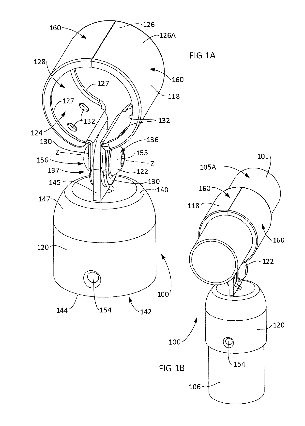
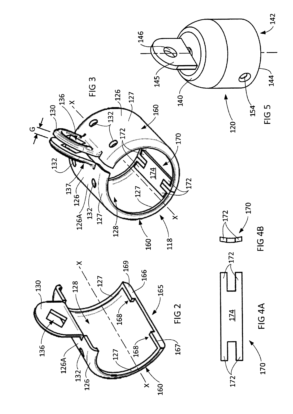
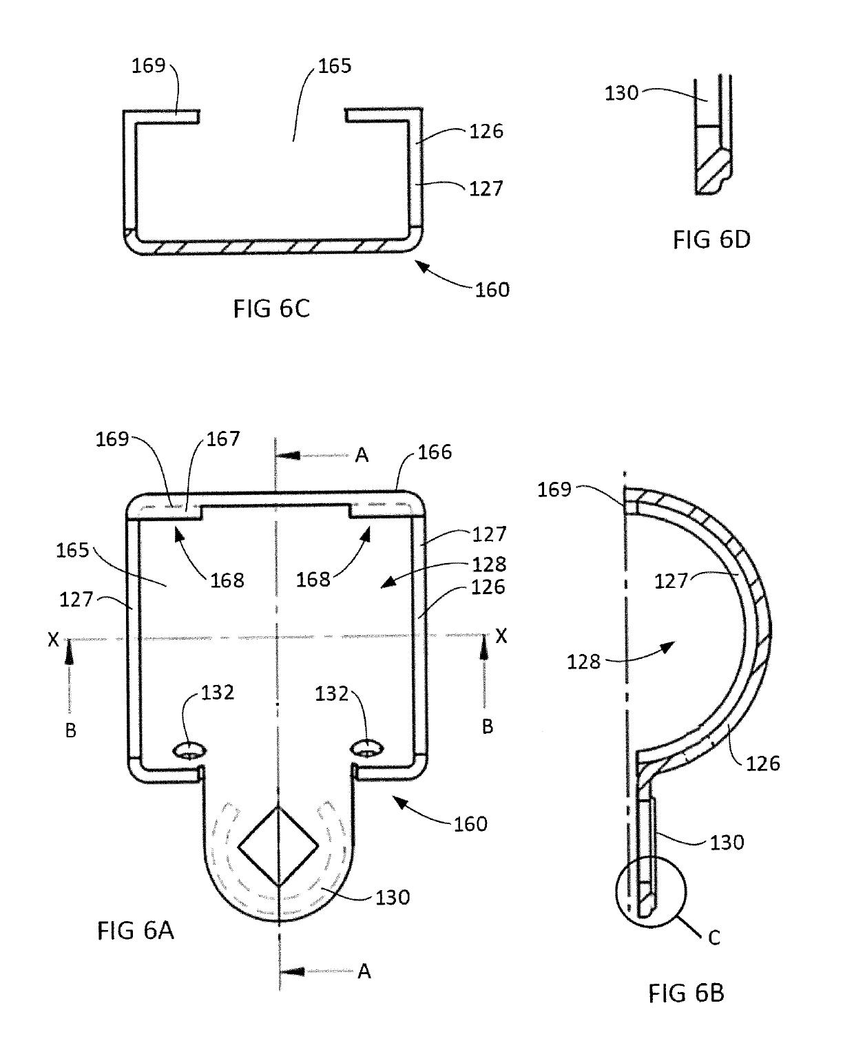
[0067]FIGS. 1A to 6 illustrate a connection fixture 100 and parts thereof according to the present invention. FIGS. 1A and 1B shows the overall assembled connection fixture. FIGS. 2 to 6 show various aspects of the component parts of the connection fixture 100. More particularly, FIGS. 2 to 4, 6 to 10 shows the features of the multipart (interconnectable two section) mounting fixture 118 according to other embodiments of the present invention.

[0068]The illustrated connection fixture 100 includes three interconnected components or sections, being a mounting fixture 118, a receiving element 120 and a connector 122.

[0069]The illustrated mounting fixture 118, in an assembled form, is a tubular collar configured to be fastened around a section of a tubular member, such as tubular pole 105 (FIG. 1B). In this regard, the mounting fixture 118 includes a tubular sleeve 126 having tubular walls 126A configured to encircle and engage with the outer surface 105A (FIG. 1B) of a tubular pole 105 ...

second embodiment

[0084]Firstly turning to the mounting fixture 218 illustrated in FIGS. 7(A) and 7(B). This mounting fixture 218 is similarly formed from two symmetrical fixture sections 260 (one of which is shown in FIG. 7(B)). Each fixture sections 260 comprise half of the mounting fixture 218. Each fixture sections 260 is rotatably (180 degrees) symmetrical relative to the other fixture section 260 enabling a single fixture section mould to be used for both fixture sections. In this embodiment the two fixture sections 260 are interconnectable using a two fingered comb connecting arrangement 270 to form the mounting fixture 218 as shown in FIG. 7(A).

[0085]FIG. 7(B) illustrates one fixture section 260. Each fixture section 260 comprising one half of the mounting fixture 218, providing a generally half tubular section having a central axis X-X corresponding to the central axis X-X of the mounting element 218. The comb connecting arrangement 270 is located at one radial end relative to the central ax...

fourth embodiment

[0092]the mounting fixture 418 of the present invention is illustrated in FIGS. 9(A) and 9(B). This mounting fixture 418 is formed from two fixture sections 460A and 460B as shown in FIG. 9(B). However, in this case the fixture sections are not symmetrical but rather are mirror images of each other due to the axially angled connector flange 430A and 430B. Nevertheless, like the previous embodiments each fixture sections 460A and 460B comprise half of the mounting fixture 418 and are interconnectable using a fingered connecting arrangement 470 to form the mounting fixture 418 as shown in FIG. 9(A). In this case, the connecting arrangement 470 has a single connecting finger.

[0093]FIG. 9(B) illustrates each fixture section 460A and 460B. Each fixture section 460A and 460B comprises a generally half tubular section having a central axis X-X corresponding to the central axis X-X of the mounting element 418. The connecting arrangement 470 is located at one radial end relative to the centr...


PUM


Abstract

A mounting fixture for interconnecting at least two tubular members, the mounting fixture including:at least one first connection section including a first connection aperture for receipt of a connector configured to secure a receiving element to the mounting fixture via a second connection aperture of the receiving element;a mounting sleeve configured to be secured around a section of a tubular member, the mounting sleeve comprises at least two interconnectable fixture sections, each fixture section comprising a portion of the mounting fixture which includes a section of the mounting sleeve and a portion of the first connection section; andat least one connecting arrangement for interconnecting adjacent fixture sections to form the mounting sleeve, each connecting arrangement being located on or within an inner side of each fixture section of the mounting sleeve to interconnect each fixture section to an adjoining fixture section at a location on or within an inner side of the mounting sleeve.

Description

PRIORITY CROSS-REFERENCE[0001]The present application claims priority from Australian provisional patent applications No. 2014904736 filed 24 Nov. 2014, No. 2015900737 filed 3 Mar. 2015 and No. 2015902114 filed 5 Jun. 2015.TECHNICAL FIELD[0002]The present invention generally relates to a mounting fixture for a connection fixture and a connection fixture including that mounting fixture. The invention is particularly applicable as part of an adjustable connection fixture for interconnecting tubular members of a fence structure or tubular railing sections of a hand rail and it can be convenient to hereinafter disclose the invention in relation to that exemplary application. However, it is to be appreciated that the invention is not limited to that application and could be used for connecting tubular sections in various other structures such as balustrades, railings, hand rails, or the like.BACKGROUND TO THE INVENTION[0003]The following discussion of the background to the invention is i...

Claims


Application Information

Patent Timeline
Patent Type & Authority Patents(United States)
IPC IPC(8): F16B7/04E04H17/14E04F11/18F16B2/10
CPCF16B7/0486E04F11/18E04F11/1817E04H17/14F16B2/10E04F2011/1821E04F2011/1868E04H2017/1482E04F2011/1819E04H17/1482
Inventor MILNER, WAYNE RUSSELLDIENER, RUDOLF ALEXANDER
Owner MILNER WAYNE RUSSELL
Why Eureka
Try Eureka