High angle tethered slide with freefall drop and variable radius swing

a high angle, swinging technology, applied in swings, amusements, sports apparatus, etc., can solve the problems of limited power supply, limited space, and inability to permit large entertainment rides

Active Publication Date: 2019-08-13
BUTTERCUP BUSINESS INC
View PDF4 Cites 4 Cited by
  • Summary
  • Abstract
  • Description
  • Claims
  • Application Information

AI Technical Summary

Benefits of technology

[0006]This disclosed apparatus was developed initially to provide an amusement ride in a limited area using nothing more than human power, while providing a multitude of sensory experiences in rapid succession in a high angle environment safely and with a minimum number of operators.
[0008]The disclosed system can be augmented by adding a baffle device which, when hung in front of the activity deck, adds excitement by shrouding the passenger in darkness as they fall through it, while at the same time, creating noise and disorientation as they travel within the baffle device, adding to the experience, but also adding a secondary benefit of slowing down the descent and directing the participant into a smaller and more controlled arc, as well as adding a sudden free-fall style drop at the end of the baffle experience.
[0009]A second system adds a traverse component and end swing to the primary drop component and includes a single traverse line or a self-equalizing dual line safety system, as previously described in U.S. Pat. No. 8,505,264. The participant is attached to a carriage with a determined length of rope / cable tether. From an end of an upper platform, the operator pushes the carriage system, which causes the passenger to be pulled off the deck and down into a baffle system. The baffle system causes the same effect described above, shrouding the participant in darkness while slowing the participant down and changing their vector so that, upon exiting from the baffle system, the participant is caused to make a short and controlled drop with required forward momentum in order to complete the traverse at the required velocity.

Problems solved by technology

Certain settings are space limited and do not permit large entertainment rides.
Moreover, some settings have limited access to power.

Method used


Image

  • High angle tethered slide with freefall drop and variable radius swing
  • High angle tethered slide with freefall drop and variable radius swing
  • High angle tethered slide with freefall drop and variable radius swing

Examples


first embodiment

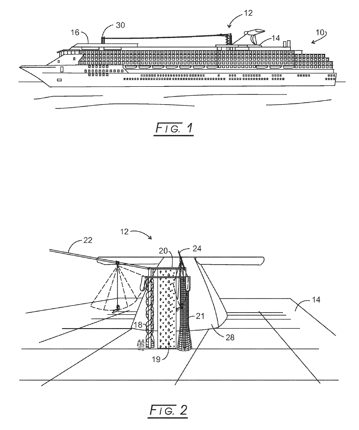
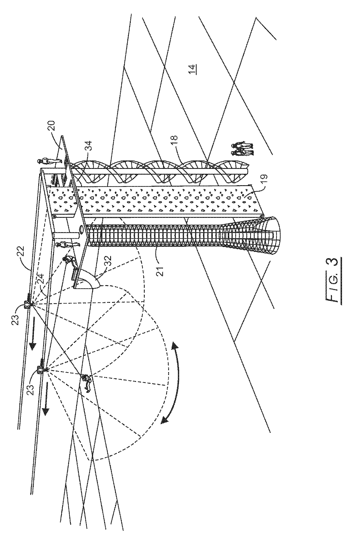
[0035]The embodiment shown in FIG. 6 eliminates the dual cables of the first embodiment, but retains the remainder of the experience. That is, the participant can access platform 20 in the same manner described above using spiral staircase 18, moving climbing wall 19, or next 21. Once the participant is located on upper platform or deck 20, the participant puts on the same harness system and is hooked to a tether, 25, that runs through a pulley, 46, located at the end of an extend arm system, 44, located atop a pair of columns, 40 and 42, that each are supported by deck 20.

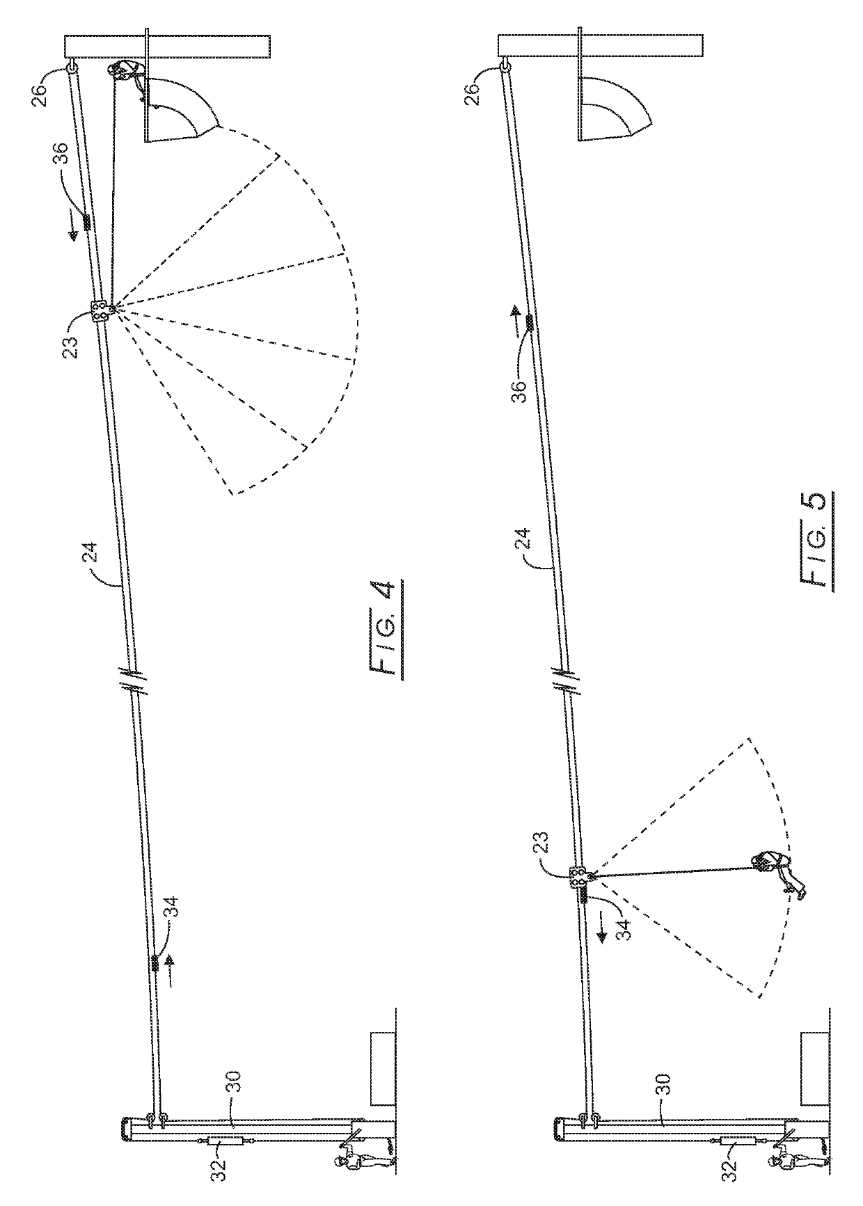
[0036]The participant is seated at the throat of slide 32 and prepares for launch. The operator pulls on tether 25 through a belay device, 49, which shortens the distance between the participant and fixed pulley 46. The radius of slide 32 is such that tether 25 becomes slightly slack as the participant proceeds down slide 32. The slide can be formed from polymeric material or fabric and suspended by flexible membe...

second embodiment

[0037]Referring now to FIGS. 7 and 8, a drop seat is illustrated for use with the first described embodiment; although, it can be used with both embodiments disclosed herein. In particular, the participant is hooked up to a harness system, gloves, etc., as described above. In this embodiment, however, the participant is seated in a drop chair assembly, 52, composed of a back, 54, fitted with a series of rollers, 56, and a seat, 58, also fitted with a series of rollers, 60. Drop chair assembly 52 is attached to a conveyor belt or similar mover, 62, that moves drop chair assembly 52 to move from an initial or home position where the rider first sits upon it to a launch position (shown in phantom in FIG. 8 with prime numbers for the corresponding parts described above). Upright back 54 of drop chair assembly 52 is pivotally connected to seat 58 of drop chair assembly 52. The operator can simply push drop chair assembly 52 to move it from the home position to the launch position shown i...


PUM


Abstract

An amusement ride is formed from a self-equalizing dual line affixed to a pulley at its upper end and to pulley and counterweight system at its lower end. An upper platform at the upper dual line end launches a rider who is connected via a line to a pulley riding on the dual line. A slide is carried by the upper platform from which the rider is launched, resulting in the rider swinging in an arcuate motion about the pulley. A belay, carried by the dual line, is movable to confront the pulley as the rider is carried down the dual lines and to enhance the arcuate swinging of the rider. A lower landing permits the rider to demount the amusement ride.

Description

CROSS-REFERENCE TO RELATED APPLICATIONS[0001]NoneSTATEMENT REGARDING FEDERALLY SPONSORED RESEARCH[0002]Not applicable.BACKGROUND[0003]This disclosure generally relates to the amusement field and more specifically to amusement or recreational rides. Certain settings are space limited and do not permit large entertainment rides. Moreover, some settings have limited access to power. For such settings, compact amusement rides requiring little to no power are required. Such settings can be in remote locations away from the electrical grid, such as aboard a luxury cruise liner.[0004]Modern cruise liners offer a variety of entertainment, which now includes amusement-type rides, such as water slides. There is, thus, a need to provide an amusement ride that can successfully operate in a limited area (small footprint) using little to no power, while providing a high thrill value to the rider. It is to such need that the disclosed apparatus is addressed.[0005]An improved canopy tour ride is di...

Claims


Application Information

Patent Timeline
Patent Type & Authority Patents(United States)
IPC IPC(8): A63F9/00A63G31/04A63G31/00B61B7/00A63B69/00A63G21/02A63G21/16A63G21/22B61B12/02A63G9/00A63G9/12
CPCA63G31/00A63B69/0048A63G9/00A63G9/12A63G21/02A63G21/22A63G31/04B61B7/00B61B12/02B61B12/022A63G21/16A63G2031/002
Inventor HRENIUK-MITCHEL, DARREN W.
Owner BUTTERCUP BUSINESS INC
Why Eureka
Try Eureka