
Central tire inflation system
a tire inflation system and tire inflation technology, applied in the direction of tire measurement, tyre parts, transportation and packaging, etc., can solve the problem that the target tire pressure inflation would require a so as to avoid unnecessary activation or repeated activation of the compressor
- Summary
- Abstract
- Description
- Claims
- Application Information
AI Technical Summary
Benefits of technology
Problems solved by technology
Method used
Image

Examples
Embodiment Construction
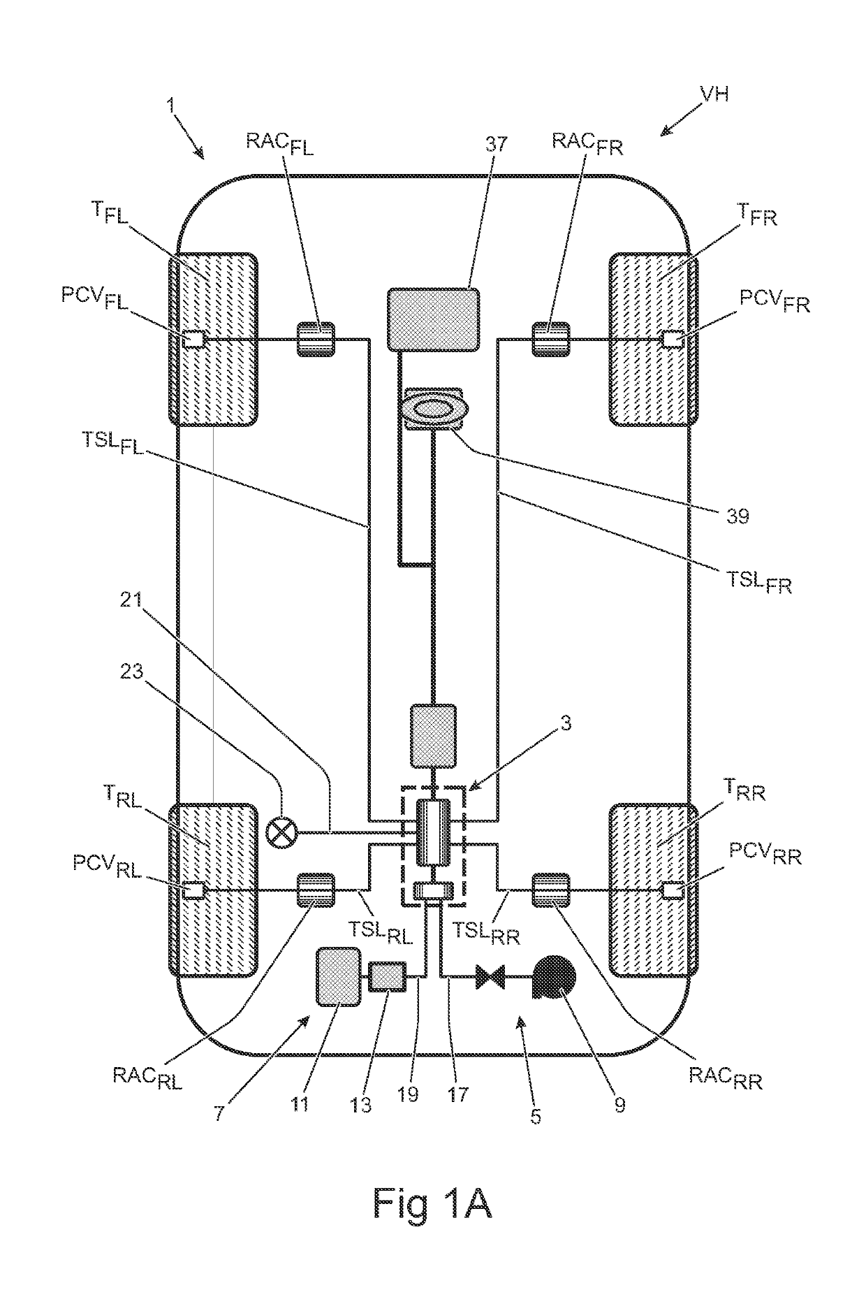
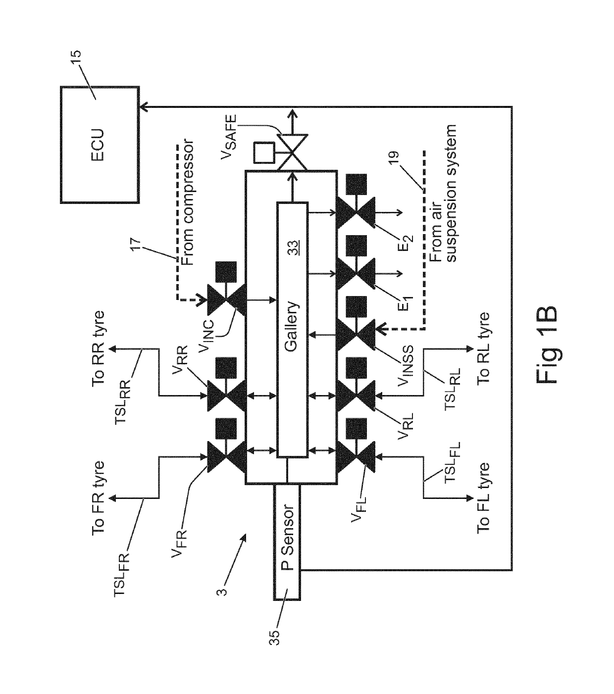
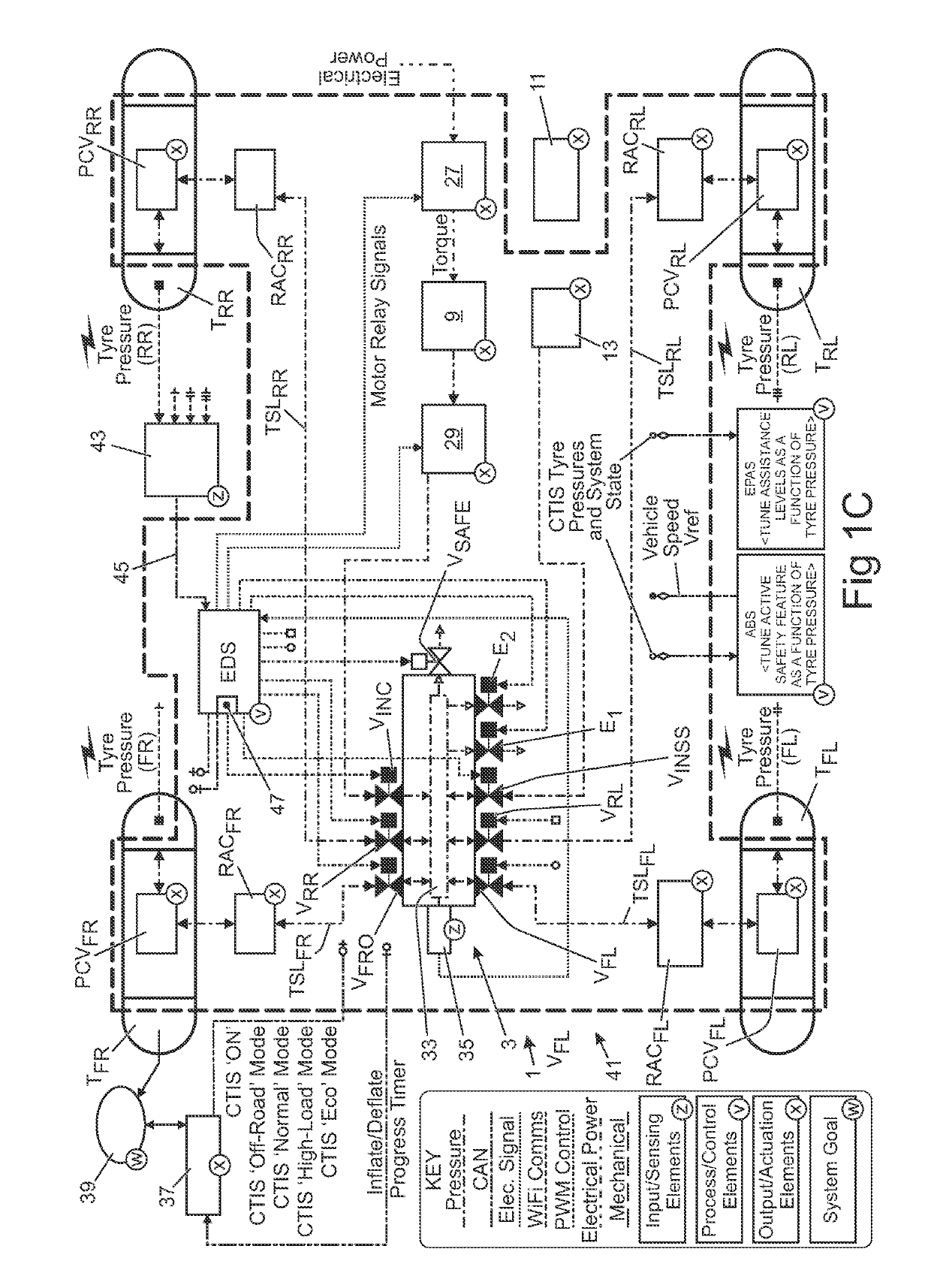
[0055]In the following description and in the drawings, reference letters are used to collectively or un-specifically identify equivalent or essentially equivalent components. Where necessary, a specific component in a collection of equivalent or essentially equivalent components is identified by suffixing a reference letters in subscript format.
[0056]A central tire inflation system (CTIS) 1 in accordance with an embodiment of the present invention will now be described with reference to the accompanying Figures. As shown schematically in FIG. 1A, the CTIS 1 is installed in a vehicle VH having four wheels W each having a tire T mounted on a wheel hub (not shown). The wheels W (and the tires T) are identified herein based on their relative position on the vehicle VH, namely: front left (FL), front right (FR), rear left (RL) and rear right (RR). This nomenclature is employed to identify the components of the CTIS 1 associated with the respective tires T. The front tires TFR, TFL are m...
PUM
 Abstract
Description
Claims
Application Information