Cutlery dispenser

a dispenser and cutlery technology, applied in the field of cuttinglery dispensers, can solve the problems of utensils exposed not only to airborne contaminants but also to contamination, and components are typically unused and simply discarded, and achieve the effect of efficient and reliable operation

Active Publication Date: 2019-09-17
RECYCLINE
View PDF43 Cites 10 Cited by
  • Summary
  • Abstract
  • Description
  • Claims
  • Application Information

AI Technical Summary

Benefits of technology

[0013]In view of the foregoing, the present inventors set forth with the basic object of providing a dispenser for utensils that is efficient and reliable in operation.
[0014]Another object of the invention is to provide a utensil dispenser that permits utensils to be loaded, retained, and dispensed conveniently and hygienically.
[0015]A further object of the invention is to provide a utensil dispenser that reduces waste and provides a mechanism for inventory control by effectively dispensing one utensil of a selected type per actuation.
[0016]Still another object of embodiments of the invention is to provide a utensil dispenser that can be loaded with stacks of utensils to be dispensed quickly and conveniently and in a manner that prevents contamination of utensils during loading, retention, and dispensing.

Problems solved by technology

A number of issues have been recognized with respect to such cutlery, particularly where it is available to consumers on a self-service basis.
Those components are typically unused and simply discarded.
Still further, while the contents of the pouches may indeed be maintained in a sanitary manner, there is no such guarantee for the pouches themselves, which may well be rummaged through by multiple customers of varying hand cleanliness before being selected by the ultimate user.
However, the utensils are exposed not only to airborne contaminants but also to contamination and, perhaps equally importantly, the perception of contamination deriving from innumerable consumers, each of unknown cleanliness, reaching into the pile of utensils to obtain the one he or she ultimately selects.
Furthermore, this method of dispensing cutlery permits the consumer to grab multiple utensils by the handful thereby leading to further expense for the establishment.
Still further, where potentially hundreds of utensils rest in a single bin, a contamination event, such as a spill or the like, may require that the entire contents of the bin be disposed of, which leads to still further waste.
For example, it was necessary for the sharp tip of the plunger to engage the utensil to be dispensed in a direct, endwise relationship, which was challenging at best and would vary in degree of practicality depending on the type of utensil to be dispensed.
Moreover, requiring the plunger not only to press a given utensil backwardly but also to lift an entire stack of utensils, which could itself be jammed or otherwise difficult to move, introduced another source of malfunction.
Diemer's and other utensil dispensers of the prior art are vulnerable to malfunction.
However, the '694 patent is interpreted to demand the individual loading of utensils into the dispenser, which is time consuming and introduces the opportunity for incorrect loading and resultant jamming.
Further, with individual handling, a further source of contamination is introduced.
Other utensil dispensers of the prior art are similarly limited.
With the requirement of a cartridge, additional expense and complication are introduced.
Such systems thus increase the inconvenience and cost of supplying cutlery to the consumer.
Many of the foregoing and other utensil dispensers of the prior art are complex in structure and operation.
Such complexity leads to excess expense in manufacture and purchase.
Furthermore, structurally complex dispensers are prone to malfunction and can be complex in usage and repair.
With that, adhesive strips, adhesive itself, or other bonding material is introduced into the system, which adds further complication and another source of potential malfunction.
Furthermore, residual adhesive left on an article of cutlery may well give the impression to the consumer that the article of cutlery that was sought to be hygienically retained and individually dispensed is less than sanitary.
This introduces still further expense in tooling and manufacture.

Method used


Image

  • Cutlery dispenser
  • Cutlery dispenser
  • Cutlery dispenser

Examples


Embodiment Construction

[0057]The utensil dispenser disclosed herein is subject to a wide variety of embodiments. However, to ensure that one skilled in the art will be able to understand and, in appropriate cases, practice the present invention, certain preferred embodiments of the broader invention revealed herein are described below and shown in the accompanying drawing figures.

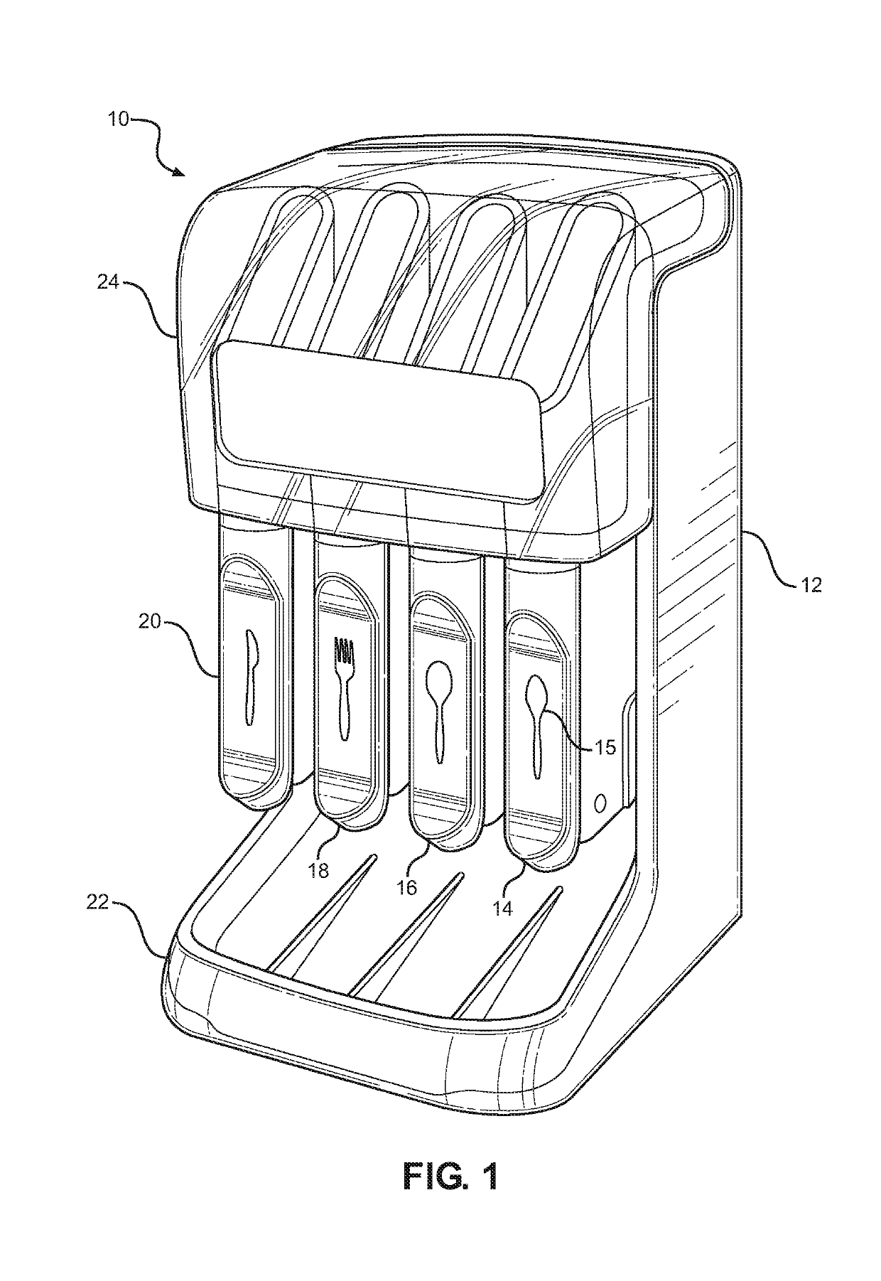
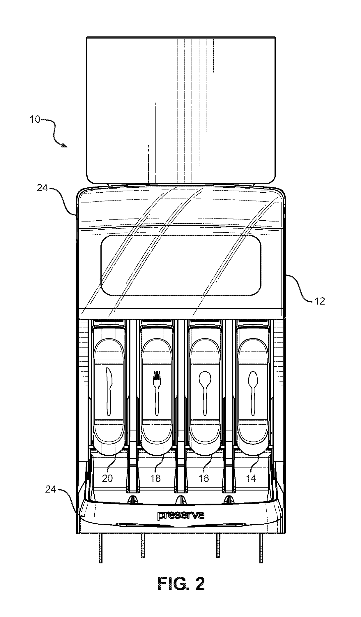
[0058]Looking more particularly to the drawings, a utensil dispenser according to the disclosed invention is indicated generally at 10 in FIGS. 1 and 2. There, the utensil dispenser 10 is founded on a main housing 12. The housing 12 retains a plurality of utensil dispensing chambers 14, 16, 18, and 20. Representations 15 indicative of the utensils to be retained are disposed on each of the dispensing chambers 14, 16, 18, and 20.

[0059]In the depicted embodiment of FIGS. 1 and 2, the dispensing chambers 14, 16, 18, and 20 are respectively constructed for the retention and dispensing of cutlery, specifically teaspoons, soup spoons, ...


PUM


Abstract

A utensil dispenser that selectively dispenses a lowermost utensil from a stack of utensils. A main housing retains plural dispensing chambers. A selectively operable dispensing mechanism has a movable support structure, an actuated support structure, and an actuation structure retained by a manual actuator. First and second arms form the movable support structure with distal portions that are in proximity to support the lowermost utensil when in a first condition and that are separated when in a second condition. A shelf member retained by the actuator forms the actuated support structure to be selectively interposed between the lowermost and second lowermost utensil. An actuation structure, such as opposed ramp surfaces, is retained by the actuator to separate the first and second arms on actuation of the actuator. When the actuator is actuated, the stack of utensils, except for the lowermost utensil, is supported so that the lowermost utensil is dispensed.

Description

FIELD OF THE INVENTION[0001]The present invention relates generally to dispensing devices. More particularly, disclosed herein is a dispenser for utensils, such as disposable or recyclable cutlery, that is efficient and reliable in operation to permit utensils to be loaded, retained, and dispensed, one utensil per actuation, conveniently and hygienically.BACKGROUND OF THE INVENTION[0002]Disposable and recyclable utensils, such as plastic spoons, forks, knives, and hybrids thereof, are frequently provided to customers, employees, students, and others in informal settings, such as casual restaurants, take-out eateries, and school and business cafeterias. A number of issues have been recognized with respect to such cutlery, particularly where it is available to consumers on a self-service basis. Among the most basic needs with respect to the retention and dispensing of cutlery is that the cutlery be maintained in a hygienic condition pending retrieval by a given consumer. A further nee...

Claims


Application Information

Patent Timeline
Patent Type & Authority Patents(United States)
IPC IPC(8): A47F1/10A47F1/08
CPCA47F1/085A47F1/10A47F2001/103A47F1/106
Inventor RAJASEKARAN, MOHANSZYMANSKI, AARONHUDSON, ERICLIVELY, JOHN
Owner RECYCLINE
Why Eureka
Try Eureka