Pumping device for sucking or draining fluid

a technology of pumping device and fluid, which is applied in the direction of machines/engines, positive displacement liquid engines, transportation and packaging, etc., can solve the problems of reducing the service life of the pumping device, unable to provide a double pressure relief function to release the excessive air pressure in the barrel, and unable to provide an air draining function for the conventional pumping devi

Active Publication Date: 2019-09-17
CRAFTS & CARRIERS TAIWAN
View PDF6 Cites 0 Cited by
  • Summary
  • Abstract
  • Description
  • Claims
  • Application Information

AI Technical Summary

Benefits of technology

[0015]According to the primary advantage of the present invention, the regulating member regulates the air flow of the air relief member to change and regulate the air pressure in the barrel so that fluid in an external container can be drawn into the barrel, and the fluid in the barrel can be compressed into the external container.
[0016]According to another advantage of the present invention, the air relief hole of the regulating member and the pressure relief member provide a double pressure relief function to release the excessive air pressure in the barrel so as to assure a safe operation of the pumping device.
[0017]According to a further advantage of the present invention, the air in the barrel is drained outward from the air relief hole of the regulating member when the air pressure in the barrel is increased to exceed a preset value, so that the air relief hole of the regulating member provides a further pressure relief function to release the air pressure in the barrel when the pressure relief member fails or malfunctions so as to prevent the barrel from being deformed or broken due to an excessive air pressure in the barrel.
[0018]Further benefits and advantages of the present invention will become apparent after a careful reading of the detailed description with appropriate reference to the accompanying drawings.BRIEF DESCRIPTION OF THE SEVERAL VIEWS OF THE DRAWING(S)
[0019]FIG. 1 is a partially front exploded cross-sectional view of a pumping device in accordance with the preferred embodiment of the present invention.
[0020]FIG. 2 is a locally enlarged view of the pumping device as shown in FIG. 1.

Problems solved by technology

However, the air pressure in the barrel cannot be drained outward from the barrel when the pressure relief member fails or malfunctions so that the barrel is easily deformed or broken due to an excessive air pressure in the barrel, thereby causing danger to the user.
Further, such a conventional pumping device cannot drain the air successively in a small quantity manner to release the pressure in the barrel gradually, so that the conventional pumping device does not provide a double pressure relief function to release the excessive air pressure in the barrel.
In addition, such a conventional pumping device does not have an air draining function.

Method used


Image

  • Pumping device for sucking or draining fluid
  • Pumping device for sucking or draining fluid
  • Pumping device for sucking or draining fluid

Examples


Embodiment Construction

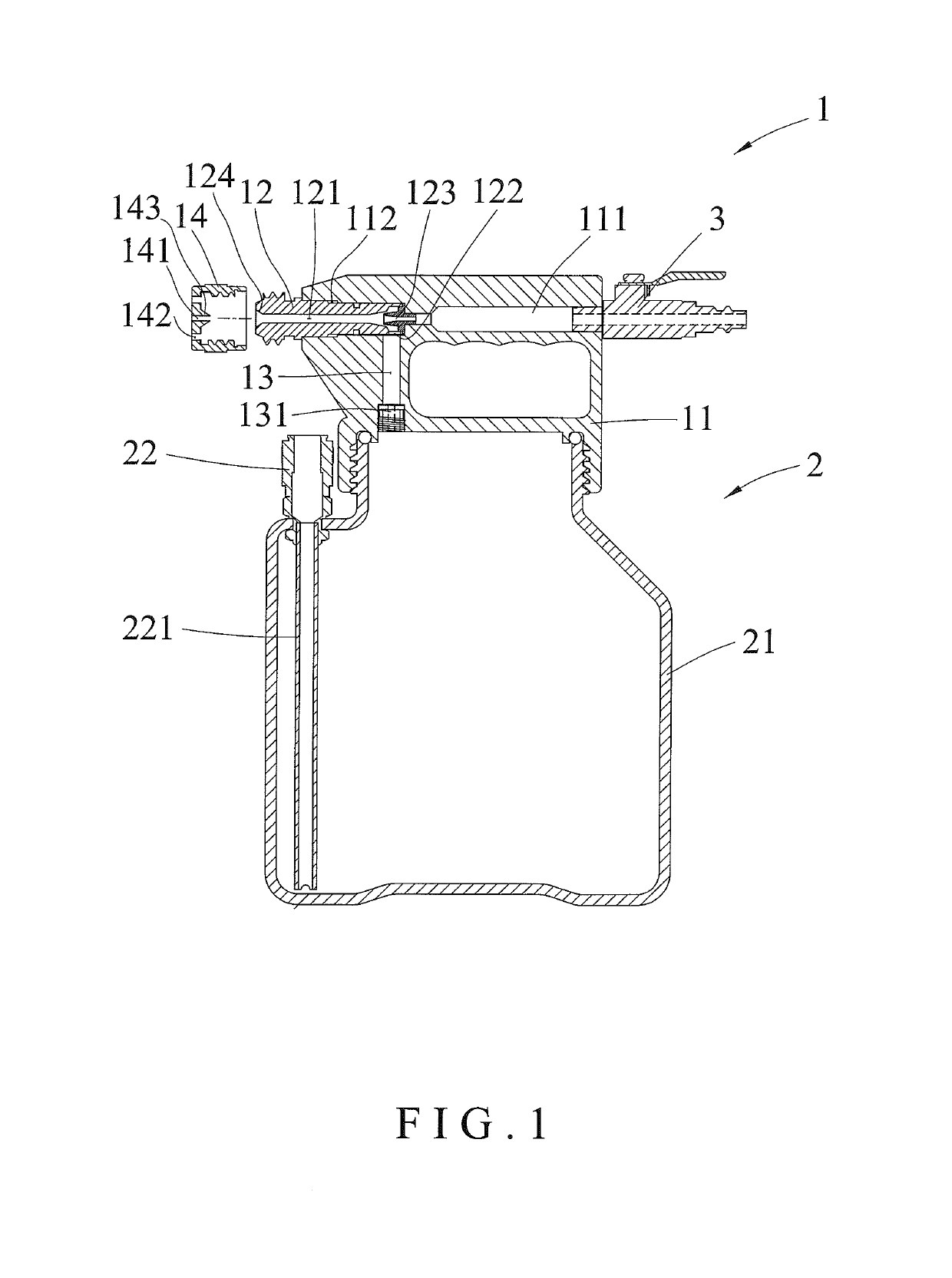
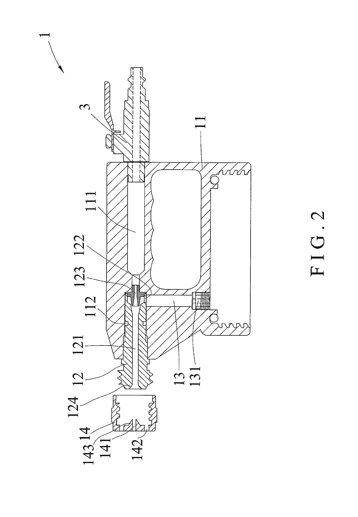
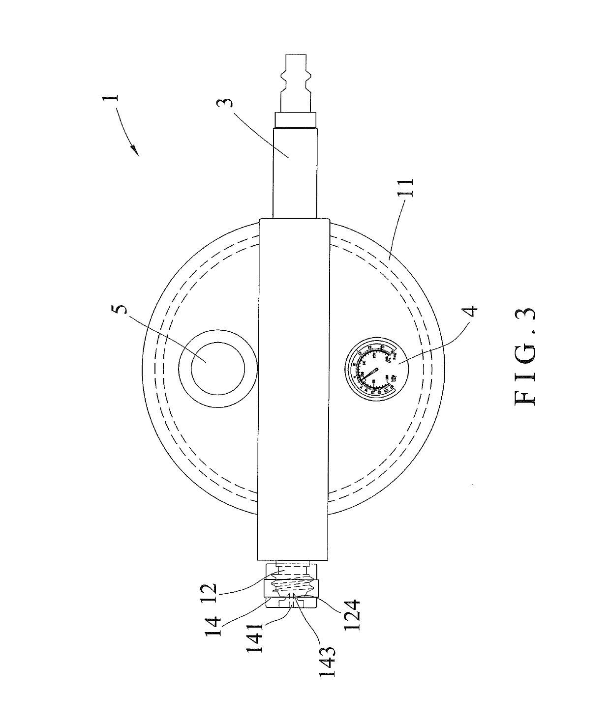
[0027]Referring to the drawings and initially to FIGS. 1-4, a pumping device in accordance with the preferred embodiment of the present invention comprises a seal cap unit 1 and a pressure barrel unit 2 combined with the seal cap unit 1.

[0028]The seal cap unit 1 includes a cap 11, an air relief member 12 connected with the cap 11, and a regulating member 14 connected with the air relief member 12.

[0029]The cap 11 of the seal cap unit 1 has a first end provided with an air inlet hole 111 and a second end provided with an air outlet hole 112. The air inlet hole 111 of the cap 11 is connected to the air outlet hole 112 of the cap 11. The air outlet hole 112 of the cap 11 has a periphery provided with a through hole 13. The through hole 13 of the cap 11 is extended through a bottom of the cap 11. The seal cap unit 1 further includes a check valve 131 mounted in the through hole 13 of the cap 11 and located between the through hole 13 of the cap 11 and the pressure barrel unit 2 to preve...


PUM


Abstract

A pumping device includes a seal cap unit including a cap, an air relief member connected with the cap, and a regulating member connected with the air relief member. The cap has an air inlet hole and an air outlet hole. The air outlet hole has a through hole. The air relief member is mounted on the air outlet hole and has a guide hole and a plurality of apertures. The regulating member has an air relief hole and a plurality of draining holes. Thus, the air relief hole of the regulating member and the pressure relief member provide a double pressure relief function to release the excessive air pressure in the barrel.

Description

CROSS-REFERENCES TO RELATED APPLICATIONS[0001]The present invention is a continuation-in-part (C.I.P.) application of the co-pending U.S. Ser. No. 13 / 798,443, filed on Mar. 13, 2013.BACKGROUND OF THE INVENTION[0002]1. Field of the Invention[0003]The present invention relates to a pumping device and, more particularly, to a pumping device for pumping a fluid, including gas and liquid.[0004]2. Description of the Related Art[0005]A pumping device is used to draw a fluid in an external container into a barrel, or to press the fluid in the barrel outward into the external container. The pumping device comprises a pressure relief member mounted on and connected to the barrel to release a portion of the air pressure in the barrel when the air pressure in the barrel exceeds a preset value so as to assure a safe operation of the barrel. However, the air pressure in the barrel cannot be drained outward from the barrel when the pressure relief member fails or malfunctions so that the barrel is...

Claims


Application Information

Patent Timeline
Patent Type & Authority Patents(United States)
IPC IPC(8): F04F5/14F04B33/00F16K5/02B05B7/24F04F5/20F04F5/52
CPCF16K5/0221F04F5/20F04F5/14B05B7/2424F04B33/00F04F5/52Y10T137/85978
Inventor WANG, KUN-WANG
Owner CRAFTS & CARRIERS TAIWAN
Why Eureka
Try Eureka