Combustion engine

a combustion engine and combustion chamber technology, applied in the direction of engine components, exhaust treatment, mechanical equipment, etc., can solve the problems of destroying the injector on each emergency stop, the post drive is not available for cooling the injector, and the destruction of the injector is therefore a serious burden, so as to ensure the safe operation of the engine

Active Publication Date: 2021-02-16
LIEBHERR COMPONENTS COLMAR SAS
View PDF7 Cites 0 Cited by
  • Summary
  • Abstract
  • Description
  • Claims
  • Application Information

AI Technical Summary

Benefits of technology

[0010]By extracting the injectors from the exhaust gas passage, the injectors are removed from their hot mounting area to a cooler area, such that an overheating of the injectors is avoided even if the cooling system of the injectors is de-energized upon activation of the emergency stop.
[0020]Thereby, the electromagnet does not have to be dimensioned to hold the spring retaining system against the entire force of the extraction spring in the retaining position.
[0027]In an embodiment of the present invention, the engine further comprises a sensor for determining that the injector is in its operation position. Thereby, a safe operation of the engine can be assured.
[0028]In an embodiment of the present invention, the engine control checks the injector position before starting the engine and / or monitors the injector position during operation. Thereby, an operation of the engine with the injector arranged in the extracted position is avoided.
[0035]In an embodiment of the present invention, the cooling system comprises a post drive for cooling the injector after a normal switch-off of the engine, wherein the emergency stop also cuts down the energy supply to the post drive. Thereby, on a normal switch-off of the engine, an extraction of the injector is not necessary, because the injector is cooled by the post drive. Only on activation of the emergency stop, where the energy supply to the post drive also has to be cut, the extraction system is activated for saving the injector.

Problems solved by technology

Therefore, the emergency stop also cuts off power supply to the cooling system of the injectors and therefore, on an emergency stop, the post drive is not available for cooling the injectors.
This will lead to a destruction of the injectors on each emergency stop.
Further, even if the emergency stop is not used during normal operation, it will at least have to be tested on commissioning of an engine.
The destruction of the injectors is therefore a serious burden.

Method used


Image

  • Combustion engine
  • Combustion engine
  • Combustion engine

Examples


Embodiment Construction

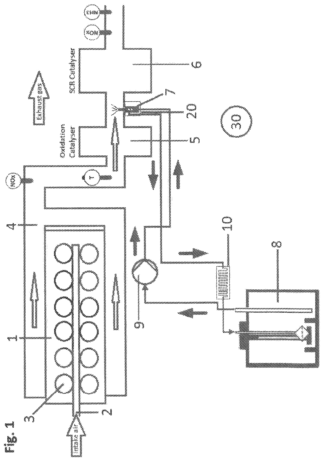
[0055]FIG. 1 shows the general configuration according to an embodiment of the present invention. The engine 1 comprises an air inlet manifold to supply air to at least one combustion chamber 3, and an exhaust gas manifold for transporting away exhaust gases from the at least one combustion chamber. In the embodiment, the engine is a reciprocating piston engine comprising cylinders as combustion chambers.

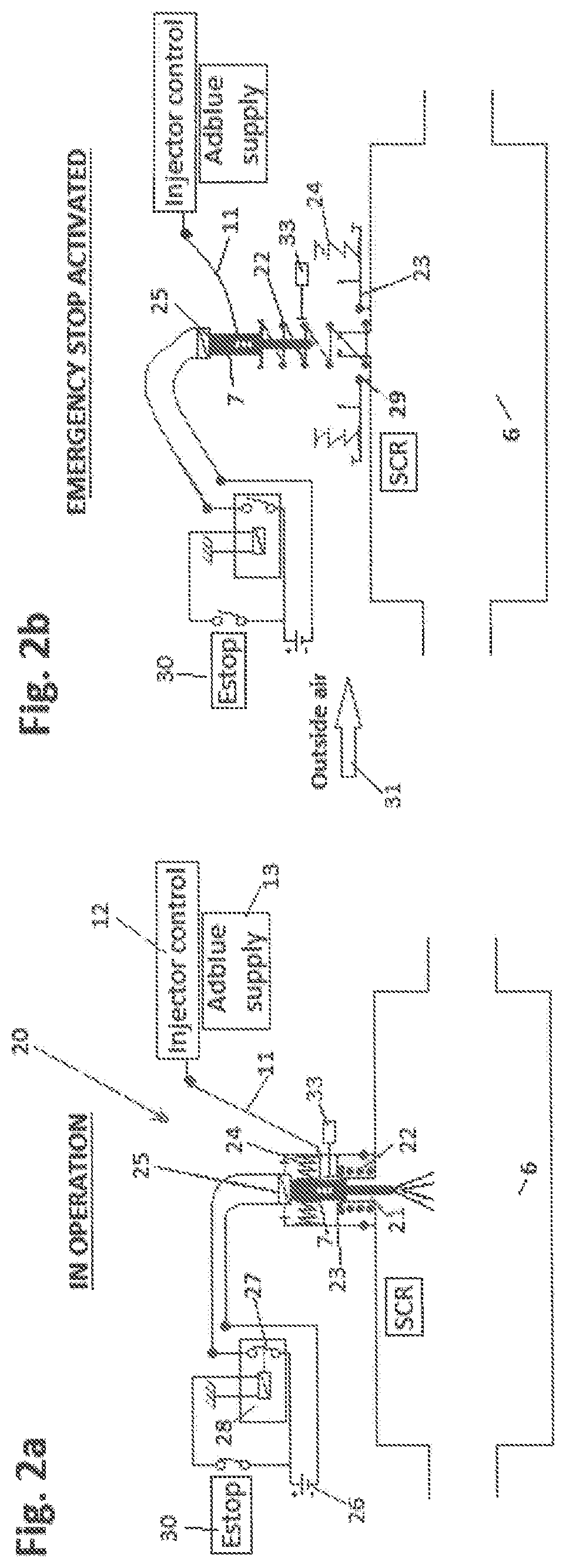
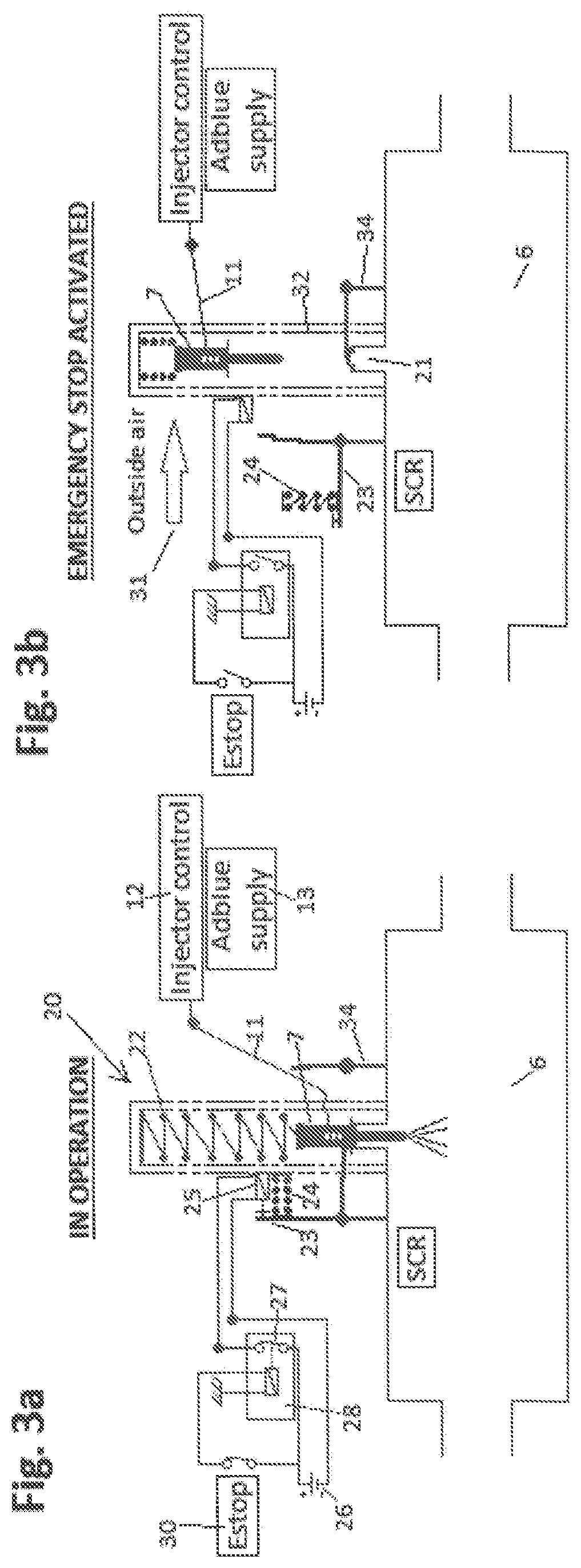
[0056]The exhaust gas manifold 4 forms an upstream part of an exhaust gas passage of the engine. In the exhaust gas passage, an exhaust gas after treatment system having at least one injector 7 for injecting a reductant into the exhaust gas passage and a catalyst 6, in particular an SCR catalyst, are provided. The reductant used in the engine may for example be a urea solution, such as AdBlue.

[0057]In the embodiment, the injector 7 is provided in an exhaust gas duct arranged upstream of the catalyst 6. In alternative embodiments, the injector could also be arranged directly on the c...


PUM


Abstract

The present invention shows a combustion engine comprising an exhaust gas aftertreatment system having at least one injector for injecting a reductant into an exhaust gas passage, and an emergency stop that cuts down the energy supply of the components of the engine upon activation, wherein the combustion engine comprises an injector extraction system that extracts the injector from the exhaust gas passage when the emergency stop is activated.

Description

CROSS REFERENCE TO RELATED APPLICATION[0001]The present application claims priority to German Application No. DE 10 2018 122 137.1 entitled “A COMBUSTION ENGINE”, filed on Sep. 11, 2018. The entire contents of the above listed application are hereby incorporated by reference for all purposes.TECHNICAL FIELD[0002]The present invention relates to a combustion engine comprising an exhaust gas aftertreatment system having at least one injector for injecting a reductant into an exhaust gas passage.BACKGROUND AND SUMMARY[0003]In an engine having such an exhaust gas aftertreatment system, the injector for injecting reductant, such as urea, into the exhaust has stream is arranged at an exhaust gas passage upstream of the SCR catalyst. The mounting area of the injector therefore has an operation temperature of between 250° C. and 540° C. depending on the load on the engine. In contrast, usual injectors only support temperatures of up to 150° C.[0004]Therefore, the injectors are cooled during...

Claims


Application Information

Patent Timeline
Patent Type & Authority Patents(United States)
IPC IPC(8): F01N13/08F01N11/00F01N3/08
CPCF01N11/002F01N3/0814F01N2290/00F01N2610/146F01N2610/1453F01N2900/1821F01N3/208F01N9/00F01N2260/20F01N2560/12F01N2590/08F01N2610/02F01N2610/11F01N2900/0414F01N2900/08F01N2900/10Y02T10/12Y02T10/40
Inventor ANSEL, MORGAN
Owner LIEBHERR COMPONENTS COLMAR SAS
Why Eureka
Try Eureka