Radio frequency filter having a resonance element with a threaded support and a planar plate including at least two through holes therein

a frequency filter and resonance element technology, applied in the field of radio frequency filter, can solve the problems of limited weight reduction and miniaturization, reduction and miniaturization of radio frequency filter cavities, etc., and achieve the effect of reducing mechanical form and size, and being easy to install

Active Publication Date: 2019-09-17
KMW INC
View PDF12 Cites 5 Cited by
  • Summary
  • Abstract
  • Description
  • Claims
  • Application Information

AI Technical Summary

Benefits of technology

[0012]As described above, a radio frequency filter having a cavity according to at least one embodiment of the present disclosure can be made more compact and lightweight. The radio frequency filter has minimized mechanical form and size required to stably fix and couple the resonance element within the cavity, and it can be made in a plain, simplified structure.
[0013]In addition, there is an advantage that the miniaturized and lightweight radio frequency filter can be easily installed in a station such as a base station.

Problems solved by technology

However, the radio frequency filter having a cavity suffers from limitations in achieving the desired weight reduction and miniaturization because the filter needs to be structured for providing a housing typically with a resonance element installed and to basically have a coupling structure of the housing with a cover.
Further, considering a filter design that reduces the overall dimension of the cavity and the resonance element for light weight and miniaturization, the mechanical shapes and sizes required to stably and fixedly couple and install the resonance element in the cavity counteract the desire for weight reduction and miniaturization of the radio frequency filter.

Method used


Image

  • Radio frequency filter having a resonance element with a threaded support and a planar plate including at least two through holes therein
  • Radio frequency filter having a resonance element with a threaded support and a planar plate including at least two through holes therein
  • Radio frequency filter having a resonance element with a threaded support and a planar plate including at least two through holes therein

Examples


Embodiment Construction

[0019]Some embodiments of the present disclosure will now be described in detail with reference to the accompanying drawings.

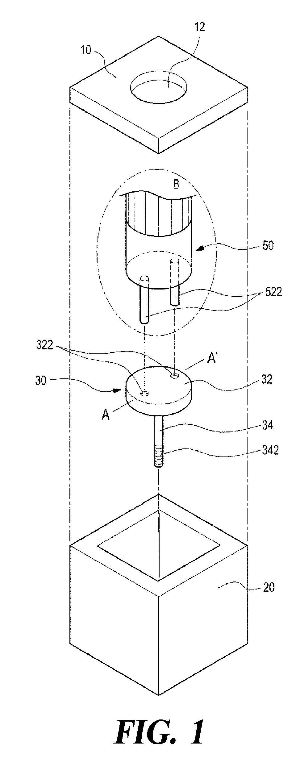
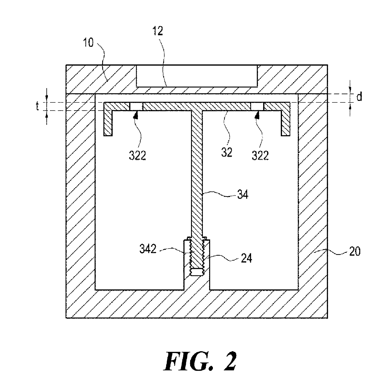
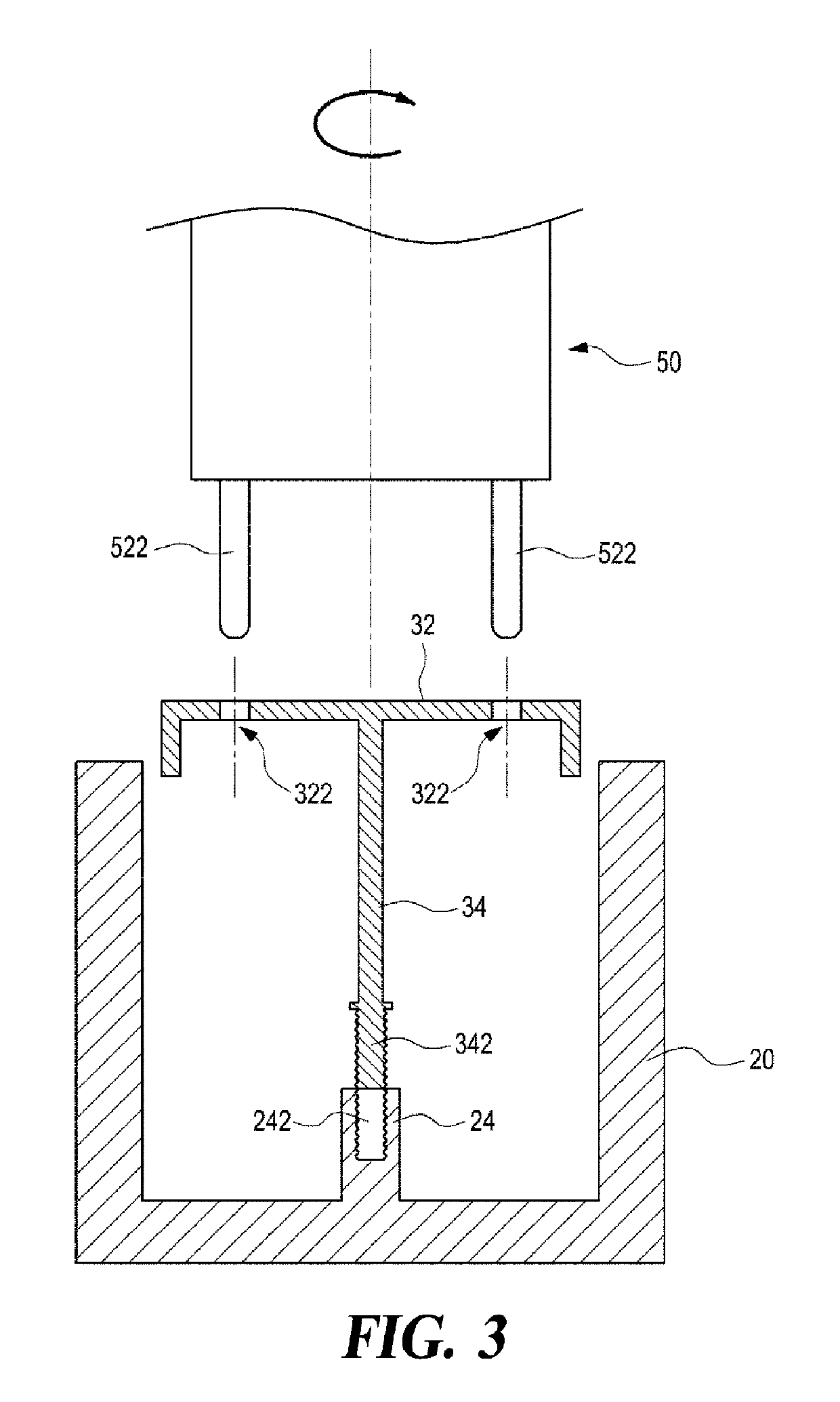
[0020]FIG. 1 is a partially exploded perspective view of a radio frequency filter having a cavity according to a first embodiment of the present disclosure, wherein the dot-dash circle B shows an additional driver device 50 as a work tool for the installation process of a resonance element 30 for the sake of convenience of explanation. FIG. 2 is a sectional view taken along line A-A′ of the radio frequency filter in FIG. 1, which is completely assembled. FIG. 3 is a diagram illustrating the installation process performed on the resonance element in the radio frequency filter in FIG. 2 before its housing 20 is fitted with a cover 10 shown in FIG. 2.

[0021]Referring to FIGS. 1 to 3, the radio frequency filter having the cavity according to the first embodiment of the present disclosure, while seemingly similar to prior art, is provided with an enclosure that has ...


PUM


Abstract

The present disclosure provides a radio frequency filter having a cavity structure including a housing, a cover and a resonance element. The housing has a hollow interior for providing a cavity, and an open side. The cover shields the open side of the housing. The resonance element is positioned in the hollow interior of the housing, and has a planar portion and a support for supporting and fixing the planar portion to the housing. The planar portion of the resonance element has at least two through holes, and the support has a lower end portion formed with a male thread structure for screw fastening. The housing is formed with a female thread structure to be screw fastened with the male thread structure formed at the lower end portion of the support.

Description

CROSS-REFERENCE TO RELATED APPLICATION[0001]This application is a Continuation of International Application No. PCT / KR2016 / 001537, filed on Feb. 16, 2016, which claims the benefit of and priority to Korean Patent Application No. 10-2015-0055070, filed on Apr. 20, 2015, which are herein incorporated by reference in their entirety.TECHNICAL FIELD[0002]The present disclosure in some embodiments relates to a radio signal processing apparatus used in a radio communication system. More particularly, the present disclosure relates to a radio frequency filter having a cavity such as a cavity filter.BACKGROUND[0003]A radio frequency filter having a cavity generally utilizes a metallic housing which provides a plurality of accommodation spaces or cavities having a shape such as rectangular parallelepiped and the like, in which dielectric resonance elements (DR) or resonance elements having a metallic resonance rod are each provided to generate super high frequency resonance. Some radio freque...

Claims


Application Information

Patent Timeline
Patent Type & Authority Patents(United States)
IPC IPC(8): H01P1/205H01P7/06H01P1/207H01P7/04
CPCH01P1/207H01P7/06H01P7/04H01P1/2053H01P1/20
Inventor PARK, NAM-SHINKIM, BYEONG-CHULJEONG, DAE-SOO
Owner KMW INC
Why Eureka
Try Eureka