Annular clamping nut for a tie bar

a technology of clamping nut and tie rod, which is applied in the direction of screw, load-modified fasteners, fastening means, etc., can solve the problems of no longer being mechanically loosened, rotor components are under a great deal of stress, and rotors in gas turbines are customarily exposed to high mechanical and thermal loads, etc., to achieve statistically reduced volume of clamping nut, high material stress, and small material tension

Active Publication Date: 2019-09-24
NORD LOCK SWITZERLAND GMBH
View PDF18 Cites 3 Cited by
  • Summary
  • Abstract
  • Description
  • Claims
  • Application Information

AI Technical Summary

Benefits of technology

[0018]Through the tensioning of the clamping nut by means of the clamping device, the tension can be at least partially taken from the clamping screws, so that they are easier to screw in and unscrew. Particularly when loosening the clamping screws to relieve the load on the tie bar provided with annular clamping nuts, less effort is required to remove said clamping nuts from the passages. In other words, due to the at least partial load-relief, the probability of these clamping screws becoming stuck is lower.
[0020]Likewise, the tensioning of the tie bar system can furthermore be gradually released, in that the preloading, for example, is at least partially released to begin with by tensioning the tie bar by means of the clamping device, so that the tension on the individual clamping screws is thereby reduced. Following this load-removal process, the individual clamping screws can be loosened, wherein a smaller force is required to loosen said clamping screws. The risk of screws sticking is thereby also substantially reduced. It is thereby possible for the tie bar system to be dismantled more easily.
[0021]The annular clamping nut according to the invention and also the clamping device, the clamping nut system and the tie bar system consequently sometimes allow quicker and simpler dismantling of the tie bar system. Because the individual clamping screws only have to be loosened with a reduced clamping force, no regreasing of the clamping screws is necessary either, as only a smaller application of force is now needed in order to turn the clamping screws.
[0026]According to a further embodiment of the invention, it is provided that the clamping nut is configured in such a manner that the passages exhibit a step-wise narrowing in the longitudinal direction. In particular, the step-wise narrowing of all passages at the same level of the clamping nuts in the longitudinal direction is provided. The step-wise narrowing allows the application of force on the clamping nut in the narrowing region via a suitably matching head of a clamping screw, so that an internal thread in the passages can also be dispensed with.
[0027]According to a further embodiment of the clamping nuts, it is provided that the external thread on the outer surface only takes up part of the outer surface of the clamping nut and, particularly in the longitudinal direction with the step-wise narrowing of the passages, is only provided at a level in the longitudinal direction at which there is a narrowed section of the passages. The application of force on the clamping nut can therefore take place on the external thread in a region where the clamping screws do not sometimes apply high material stresses to the clamping nut. Instead, a material region of the clamping nut that only exhibits smaller material tensions can be exposed to a tensioning force. In this way, the tensioning force can be distributed comparatively uniformly over the clamping nut and material fatigue over the volume of the clamping nut can be statistically reduced.

Problems solved by technology

In particular, rotors in a gas turbine are customarily exposed to high mechanical and thermal loads on account of the operating conditions.
The high temperatures of the working medium and the forces acting on the rotor when the gas turbine is operating mean that the rotor components are under a great deal of stress.
Due to the high temperatures that sometimes occur and can act on the clamping nut when the rotary engine is in operation, lubricant may escape at the clamping screws and microscopic deformations may also possibly occur, so that during maintenance work, for example, and the loosening of the clamping screws, one or more of these may become stuck so that they can no longer be mechanically loosened.
In a case of this kind which is particularly inconvenient for the rotary engine operator, it is sometimes no longer possible for the machine to be dismantled and maintenance work carried out.
In order to be able to carry out the dismantling, however, the only option available to the operator is to destroy the clamping nut in question, although this may result in the destruction of the tie bar and the entire rotary engine with it.
Furthermore, it has proved disadvantageous that during the tensioning of the tie bar the clamping force has to be applied to the clamping nut via the individual clamping screws.
Since, on the one hand, the clamping nut must exhibit many individual clamping screws of this kind in order to be able to apply the high total clamping force, the tensioning process has proved very time-consuming.
Practical considerations make this very difficult, however, as even small differences in the stroke of the individual clamping screws can lead to greatly differing clamping force loads.
These disadvantages from the state of the art illustrate that a technical solution is required so that, particularly in the case of clamping nuts with multiple clamping screws, a controlled tensioning of the tie bar system and also a controlled dismantling of the entire rotary engine is furthermore possible.

Method used


Image

  • Annular clamping nut for a tie bar
  • Annular clamping nut for a tie bar
  • Annular clamping nut for a tie bar

Examples


Embodiment Construction

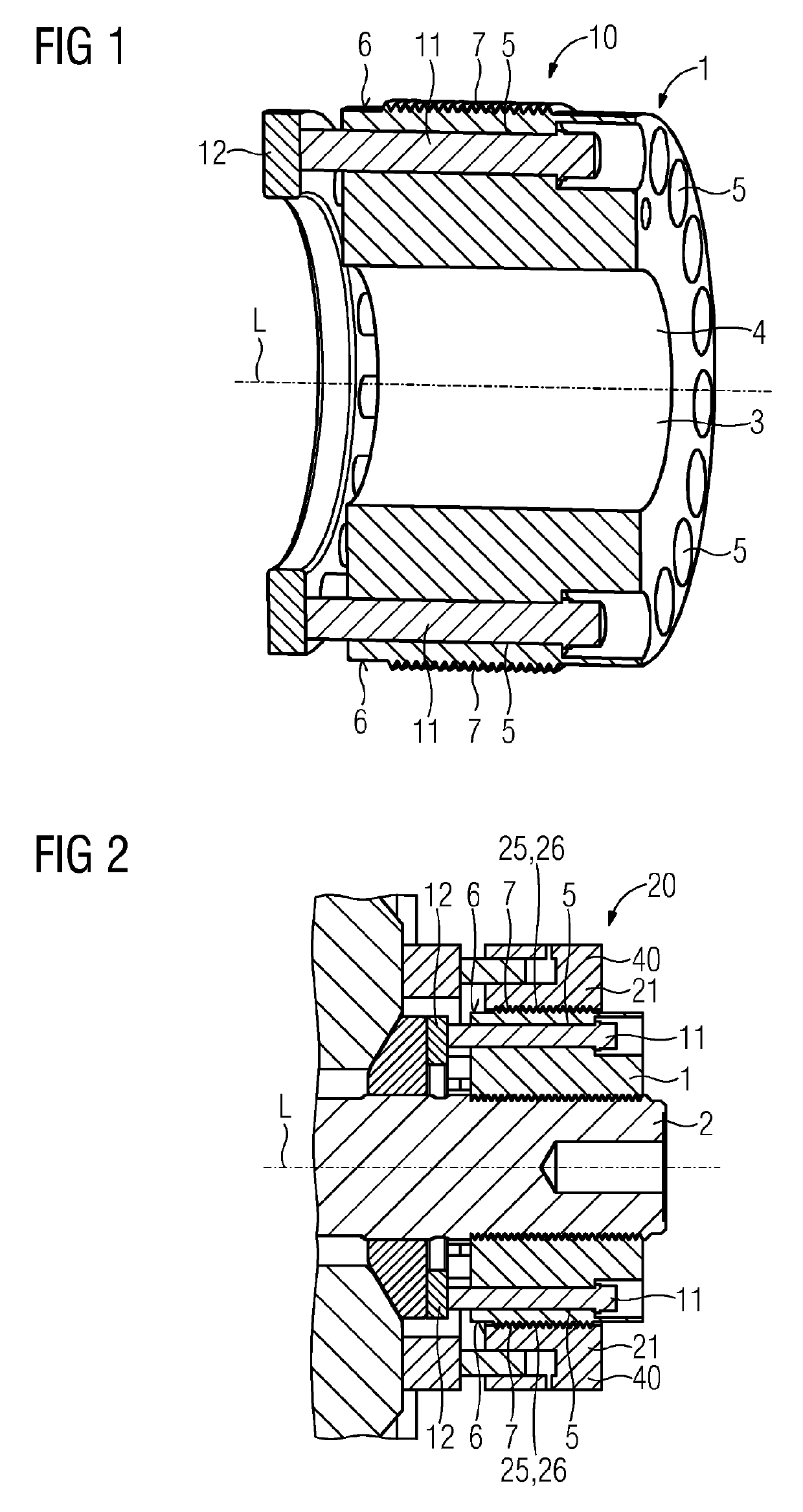
[0043]FIG. 1 shows a side sectional view through a first embodiment of a clamping nut system 10 according to the invention which, in addition to an embodiment of a clamping nut 1 according to the invention, exhibits a number of clamping screws 11 (first clamping screws 11) and also a clamping ring 12. In addition to a central recess 3 for receiving a tie bar 2 (not shown in this case) the clamping nut 1 has a number of passages 5 parallel to the longitudinal direction L represented which are arranged in uniform radial spacings in the ring circumference direction. The passages exhibit a directional course which is substantially parallel to the longitudinal direction L. Clamping screws 11 are guided through each of the passages 5, which clamping screws are in contact with a clamping ring 12 at the ends in such a manner that said clamping ring supports the ends of the clamping screws 11. The clamping ring 12 has a central recess not further provided with a reference number which is arr...


PUM

PropertyMeasurementUnit
temperaturesaaaaaaaaaa
diameteraaaaaaaaaa
tensionaaaaaaaaaa

Abstract

An annular clamping nut which is provided for being placed onto the end of a tie bar, in order to brace the latter, and which has in addition to a central recess for receiving the tie bar parallel to a longitudinal direction passages at uniform radial spacings in the ring circumferential direction which are directed parallel to the longitudinal direction of the central recess and are provided for receiving clamping screws. An external thread is provided on the outer surface of the clamping nut, which outer surface is arranged on a side which lies substantially opposite the wall of the central recess, which external thread runs substantially in the ring circumferential direction of the outer surface.

Description

CROSS REFERENCE TO RELATED APPLICATIONS[0001]This application is the US National Stage of International Application No. PCT / EP2015 / 060346 filed May 11, 2015, and claims the benefit thereof. The International application claims the benefit of German Application No. DE 102014208927.1 filed 12 May 2014 and German Application No. DE 102014219643.4 filed 29 Sep. 2014. All of the applications are incorporated by reference herein in their entirety.FIELD OF INVENTION[0002]The present invention relates to an annular clamping nut which is provided to be placed onto the end of a tie bar in order to tension said tie bar and which has, in addition to a central recess for receiving the tie bar, passages with uniform radial spacings in the ring circumference direction which are parallel to a longitudinal direction, which passages are directed parallel to the longitudinal direction of the central recess and are provided for receiving clamping screws. Furthermore, the present invention relates to a ...

Claims


Application Information

Patent Timeline
Patent Type & Authority Patents(United States)
IPC IPC(8): F16B31/00F01D5/06F01D5/02B23P15/04
CPCF01D5/066B23P15/04F01D5/026
Inventor HOFSOMMER, DANIELKOLK, KARSTENKURY, PETERRICHTER, MATTHIASSCHULZ, MICHAELSPRINGBORN, DIRK
Owner NORD LOCK SWITZERLAND GMBH
Why Eureka
Try Eureka