Closure cap for a container

a container and closure technology, applied in the field of container closure caps, can solve the problems of not being intuitive to use, not providing the consumer with the original desired effect, and expensive production of the closure caps described in the document, and achieve the effect of reliable activation protection and easy removal

Active Publication Date: 2016-06-14
INCAP INT
View PDF11 Cites 6 Cited by
  • Summary
  • Abstract
  • Description
  • Claims
  • Application Information

AI Technical Summary

Benefits of technology

[0016]In a preferred embodiment, the rotational and/or the translational movement is established by the shaping of the cap housing and of the plunger with respect to one another. According to one preferred variant, the plunger has a skirt with a bottom edge which abuts at least in part against a top edge of an outer sleeve of the cap housing. In this case, the bottom edge of the skirt and the top edge of the outer sleeve are profiled in such a manner that in the initial non-active position a translational movement of the plunger is blocked and only a rotation of the plunger into the intermediate position enables a translational movement of the plunger into the recess of the cap housing. In contrast to the prior art known from WO 2006/052827, the closure cap according to the invention consequently does not require a separate locking ring. In the non-active position, the profiling of the cap housing and of the plunger prevent an inadvertent downward actuation of the plunger and consequently prevent a piercing of the membrane. The user can therefore only produce an actuation, namely a pressing down of the plunger and consequently a piercing of the membrane, by means of initially rotating the plunger into the intermediate position. During the storage and the transporting of a container provided with such a closure ca

Problems solved by technology

As a result of the unavoidable transport and storage times, in the majority of cases these types of beverages no longer provide the consumer with the originally desired effect or

Method used


Image

  • Closure cap for a container
  • Closure cap for a container
  • Closure cap for a container

Examples


Embodiment Construction

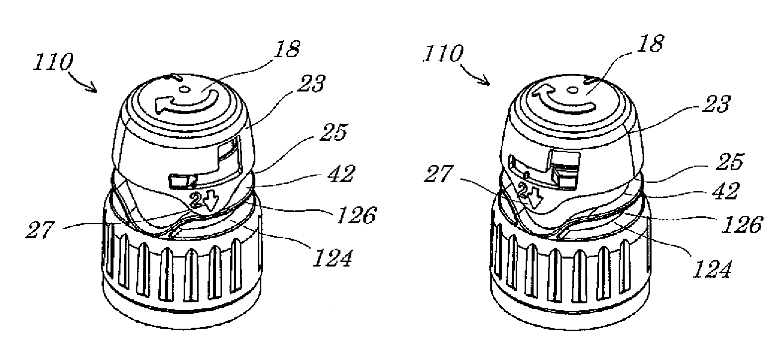
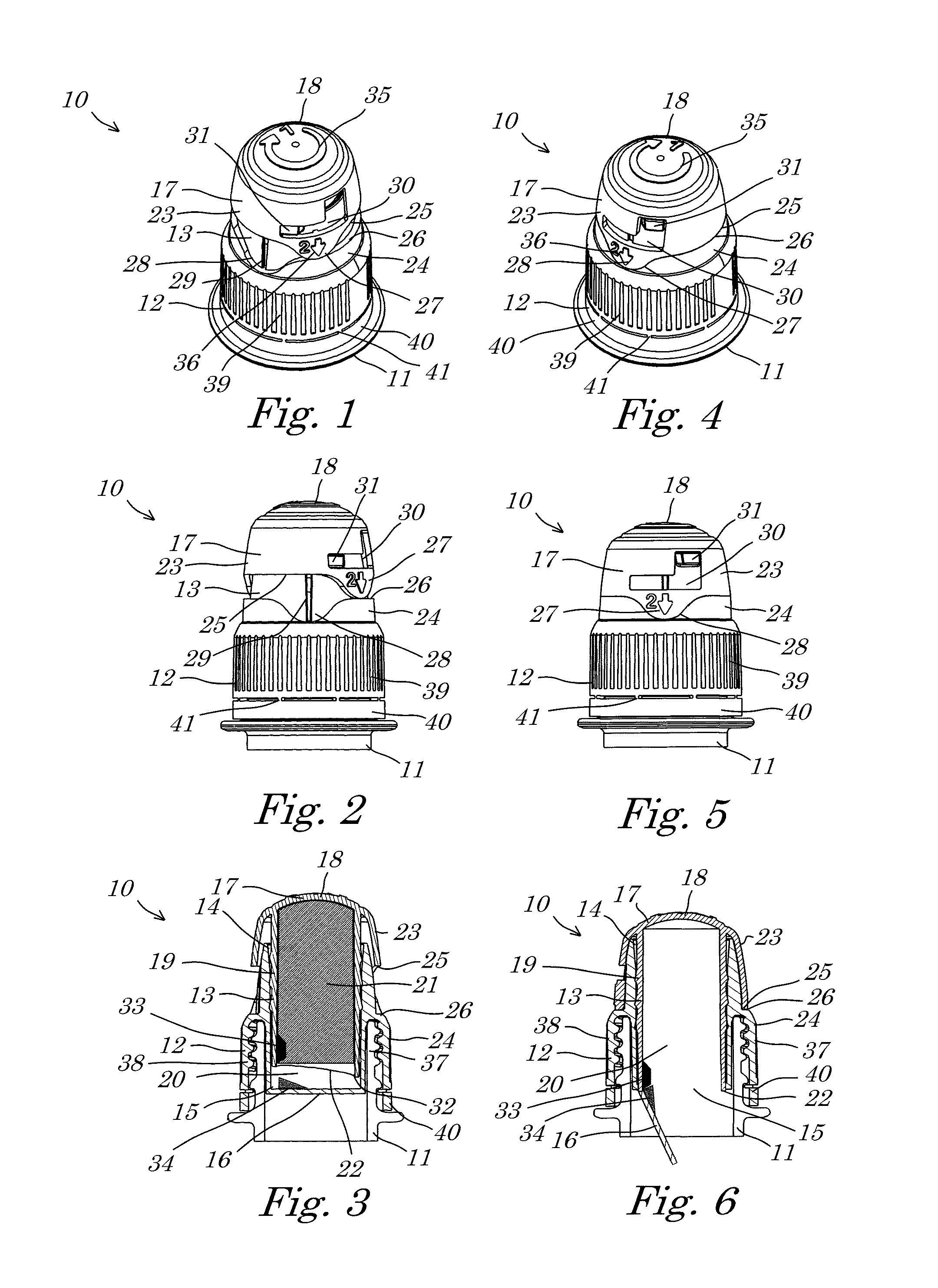
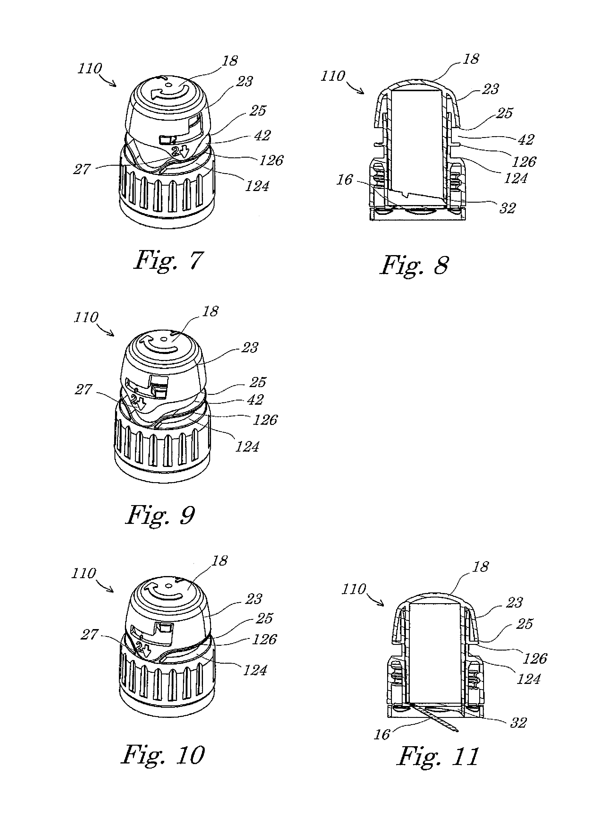
[0050]The closure cap according to a first embodiment of the invention is shown in the first, non-active position in FIGS. 1 to 3.

[0051]The closure cap, designated overall by the reference numeral 10, is fastened on a bottle neck 11 of a container, which for reasons of better clarity is not shown any further. The closure cap 10 includes a cap housing 12 which has a substantially cylindrical recess 13 which has a top opening 14 and a bottom opening 15. The bottom opening 15 is closed by means of a piercable membrane 16 such that the recess 13 is realised overall in a U-shaped manner. A plunger 17, which includes a cover 18 and a cylindrical lateral surface 19 which extends downward from the underside of the cover 18, is inserted into the recess 13. The lateral surface 19 engages in the top opening 14 of the recess 13. As can be seen in particular from the cross sectional representation in FIG. 3, the outside diameter of the lateral surface 19 corresponds substantially to the inside d...


PUM


Abstract

A closure cap for a container, said closure cap having a cap housing including a substantially cylindrical recess which has a top opening and a bottom opening, wherein the bottom opening is closed by means of a piercable membrane, a plunger comprising a cover and a substantially cylindrical lateral surface extending downward from an underside of the cover, wherein the lateral surface engages in the top opening of the recess and has an outside diameter corresponding substantially to the inside diameter of the recess, and a chamber defined by the cylindrical recess and the plunger which engages in the recess by way of its lateral surface, the plunger and the cap housing being movable relative to one another between a first, non-active position, and a second, activated position.

Description

FIELD OF THE INVENTION[0001]The present invention relates to a closure cap for a container and to a container provided with a closure cap of this type. The invention relates, in particular, to a closure cap for a container, which closure cap, in its interior, has a chamber in which a substance, for example an active substance, is kept separated from the rest of the interior of the container and, when required, in particular directly prior to use, is able to be discharged into the interior of the container. The closure cap can be used with a vast variety of containers, including bottles, drinking glasses, bowls, beakers, tumblers and the like.BACKGROUND OF THE INVENTION[0002]A plurality of substances, for example medicines or food additives such as vitamins, proteins, anti-oxidants or even vegetable additives, as an aqueous solution, aqueous suspension or emulsion have a potency that decreases rapidly with time. In particular in the area of sport and wellbeing, these types of product...

Claims


Application Information

Patent Timeline
IPC IPC(8): B65D51/28
CPCB65D51/2857B65D51/2835B65D2101/0076B65D2401/50
Inventor BURGESS, MICHAEL SEANHAUCK, AXEL
Owner INCAP INT
Why Eureka
Try Eureka