Drainage system for wounds

a wound and drainage system technology, applied in the field of wound drainage systems, can solve the problems of easy breakage, preferred treatment mode, and inability to withstand the force of glass containers, so as to prevent accidental leakage of vacuum, prevent accidental spillage, and ensure structural integrity and rigidity

Active Publication Date: 2019-10-15
PFM MEDICAL
View PDF10 Cites 5 Cited by
  • Summary
  • Abstract
  • Description
  • Claims
  • Application Information

AI Technical Summary

Benefits of technology

[0022]The container herein, employable for collection of fluid from the patient, is provided with a plurality of closure components which allow the user to seal the tube from one or both of the patient end of the tube and the engagement of the tube with the interior cavity of the container. Two such closures are especially preferred in that they help to prevent accidental leakage of the vacuum during set up, or should a tube be removed. Additionally, an anti-backflow valve may also be provided to prevent fluid flow from draining from the proximal end of the tube engaged with the patient, unless that tube is in sealed communication with a vacuum sufficient to overcome the seal provided by the backflow valve.
[0023]A Y-connector is preferably positioned at the engagement of the tube communicating with the patient, and a flexible connector engaged with the inlet of the container. The Y-connector allows for communication of the vacuum to pull fluid from the patient through one conduit and provides a first access for fluid sampling via a needle-less valve adapted for a sealed engagement with a screw on or snap on needle-less syringe. This screw on syringe engagement allows for drawing a sample of the fluid communicated from the patient, without disengaging the container, or the need to carry it to the lab. An additional needle-pierceable self sealing access membrane may be provided alone or in combination with the first access. Such is located in a lower end of the bottle to allow sampling of fluid in the bottom of the interior cavity.
[0024]The system herein provides lightweight containers or bottles formed of lightweight polymeric or plastic material for easy carrying, shipment, and storage. The walls of the container are formed in a curve or may have additional arches formed into the curved walls to provide walls with sufficient structural integrity and rigidity to withstand the a vacuum of 600 to 900 hg / mm within the interior, and thus to eliminate the need for using current heavy glass containers.
[0025]Further, the system herein provides a kit of engageable components, which provide users the option to either replace the patient-engaged container when full, or, employ a second container having an equal or slightly higher vacuum therein and sealed tubes and attachments, which allow for the draining of fluid and reinstatement of the vacuum in the patient engaged container, without the need to disconnect the patient-engaged container from the tube engaged with a patient. One or a plurality of anti-backflow or reversionary valves may also be operatively positioned in the tubing or engaged connectors to prevent accidental spillage of significant amounts of fluid from tubes and allow flow therethrough only when a sufficient vacuum is present to draw fluid therethrough.

Problems solved by technology

However, in the event of mechanical failure of the pump, or an electrical power failure causing cessation of pumping, such is not a preferred mode of treatment.
While glass walled containers are excellent in maintaining their shape under high vacuum, they suffer from a number of problems when employed in the medical field.
First, glass containers inherently are brittle on an impact and thus they break easily if dropped or struck by a glancing blow.
Such a potential for breaking can be a severe problem for the medical facility should the bottle be broken or cracked by an impact and the liquid and / or other patient body secretions from the interior cavity are communicated to the facility floor or onto a bed.
Additionally, sampling the contents of a glass bottle is not easily accomplished.
In light of the potential for breaking during transport noted above, the need to take the entire bottle to a lab, and risk spreading infection if the bottle is dropped or struck during transport, is undesirable.
Further, should a break occur, lab analysis of the patient secretions is further delayed while a new glass bottle is set up, pierced, engaged with a tube and sufficient secretions extracted.
An additional problem is from the need to use a sharp instrument to pierce the seal or cover of the single aperture of the glass bottle and quickly seal it to prevent total evacuation.
Such is first a hazard to the user who must pierce the bottle, and later to the lab personnel who must remove the piercing component to sample fluid contents.
The sharp piercing instrument can easily cut or otherwise hurt medical personnel unfamiliar with using such.
Additionally, if the cover of such a glass bottle is pierced, without first engaging a sealed tube to the piercing instrument, the vacuum in the bottle cavity can easily vent and the entire bottle rendered unusable by the entry of the exterior atmosphere immediately into the interior container.
Still further, glass containers have sidewalls which are not easily bored or drilled to allow the engagement of connectors to the bottle.
This lack of additional openings to the bottle interior limits the ability of medical processionals and other users, to simply drain the contents of the interior cavity to a secondary container while concurrently reforming the vacuum in the bottle collecting fluids from a patient.
Still further, it can be hard to discern in conventional containers if they still have sufficient vacuum onboard to continue the suction-aided draining of a patient.
This can occur when such bottles are on the floor next to the bed, which renders them hard to see from the doorway of the room, or in an overhead view, to determine their state.
Various limitations of the related art will become apparent to those skilled in the art upon a reading and understanding of the specification below and the accompanying drawings.

Method used


Image

  • Drainage system for wounds
  • Drainage system for wounds
  • Drainage system for wounds

Examples


Embodiment Construction

[0043]In this description, the directional prepositions of up, upwardly, down, downwardly, front, back, top, upper, bottom, lower, left, right and other such terms refer to the device as it is oriented and appears in the drawings and are used for convenience only; they are not intended to be limiting or to imply that the device has to be used or positioned in any particular orientation.

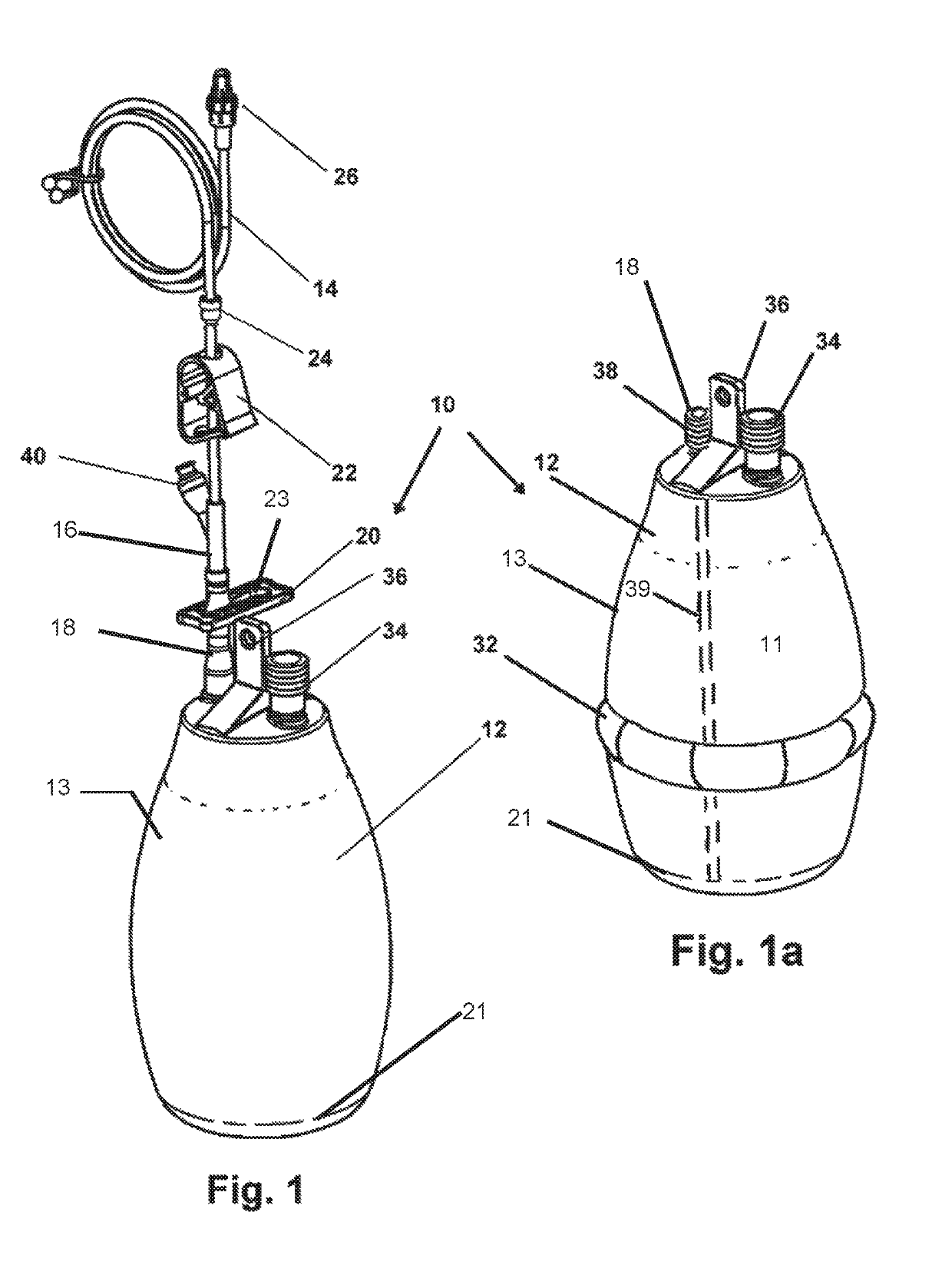
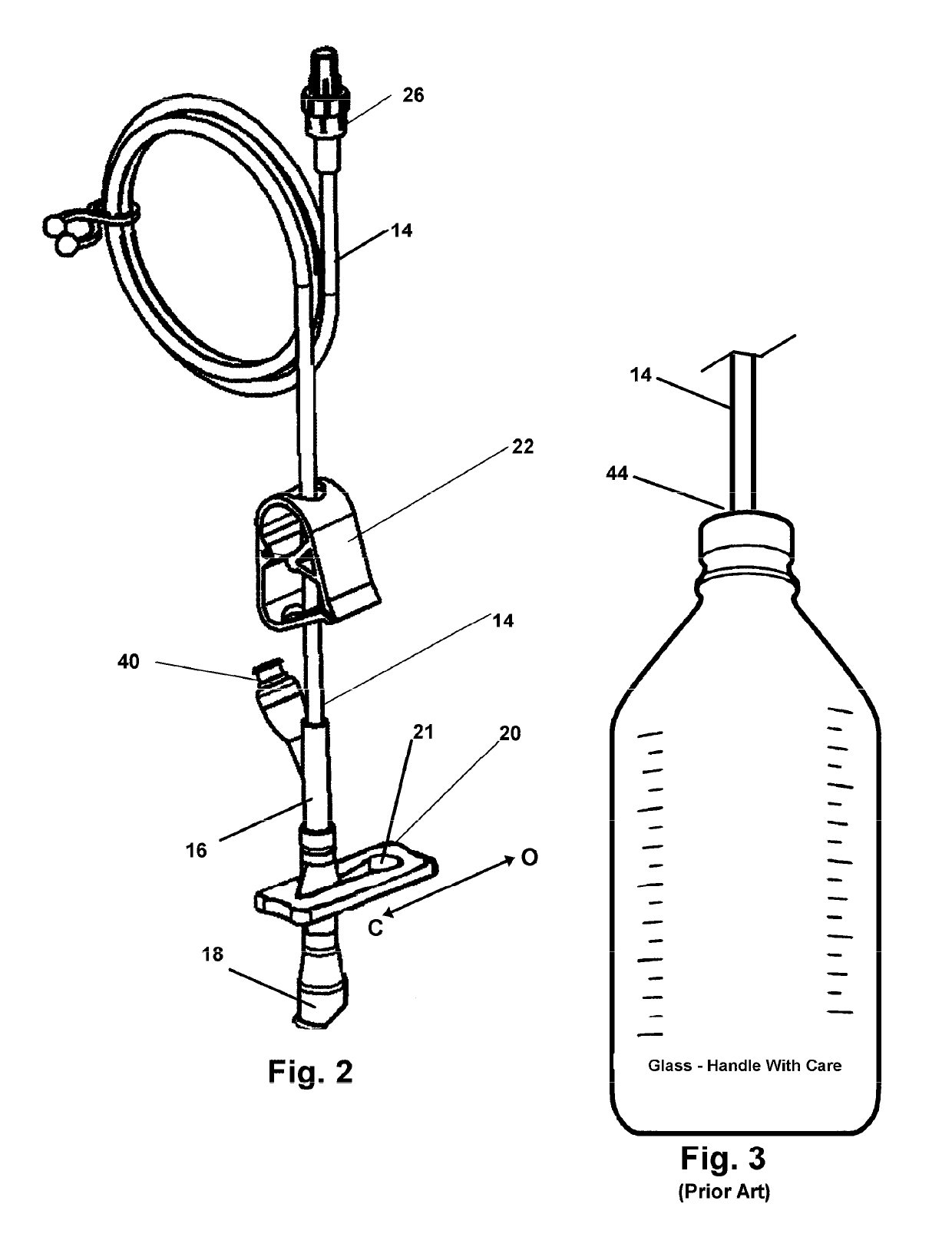
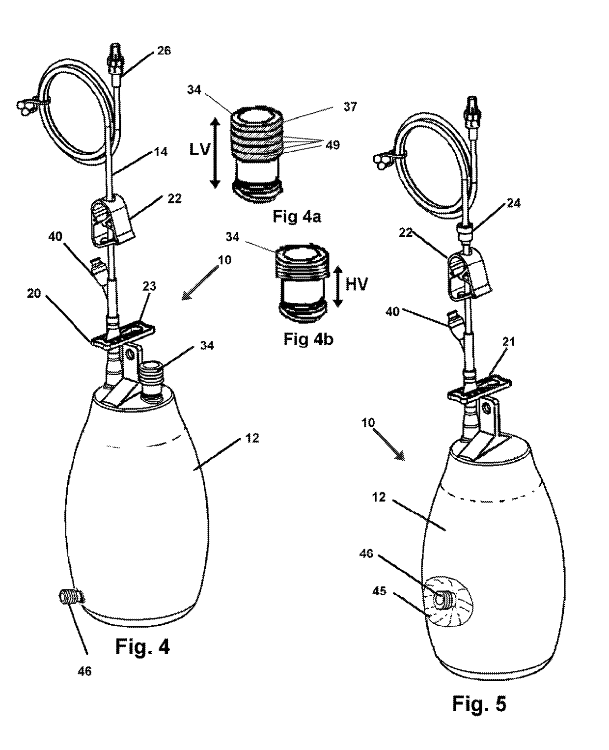
[0044]Now referring to drawings in FIGS. 1-6, wherein similar components are identified by like reference numerals, there is seen in FIG. 1, the device 10 which provides a vacuum drainage container 12 configured for an engagement with a the tube 14 or catheter at a first end in a sealed engagement. So engaged the container 12 provides for communication with the vacuum in the interior cavity of the container 12 and at a second or distal end to provide suction to the drainage conduit from the patient.

[0045]A Y-connector 16 bifurcates the tube 14 which is in sealed communication with the inlet 18 connect...


PUM


Abstract

A fluid drainage system is provided which is configured to engage with a drainage tube engaged with a drainage site with a patient. The container has an internal cavity with negative pressure to impart suction to the drainage tube and can be engaged to the drainage tube without loss of negative pressure during the process. Secondary containers may be engaged to restore negative pressure to the first container and remove fluid therefrom. Walls of the first container may be shaped to resist deflection due to high internal negative pressure.

Description

[0001]This application claims priority to U.S. Provisional Application No. 61 / 769,482 filed on Feb. 26, 2013 and is incorporated herein in its entirety by this reference.BACKGROUND OF THE INVENTION[0002]Field of the Invention[0003]The present invention relates generally to wound drainage systems for human and animal patients. More particularly, it relates to a system having one or a plurality of engageable vacuum bottles having means for sealed communication of the vacuum or negative pressure in the internal cavity of the bottle container, with the fluid to be drained from a patient and with a secondary bottle providing an auxiliary communication of negative pressure.[0004]Background of the Invention[0005]During surgery and during recovery following such surgery, and in some cases as a treatment without surgery, it frequently becomes a requirement to evacuate fluid and other liquid such as wound secretions from the body of a patient. Such removal can be from an internal organ, a sur...

Claims


Application Information

Patent Timeline
Patent Type & Authority Patents(United States)
IPC IPC(8): A61M1/00A61B10/00
CPCA61M2205/584A61B10/00A61M1/631A61M1/602A61M1/732A61M1/74A61M1/86A61M1/64A61M1/98
Inventor KERR, MARSHALL
Owner PFM MEDICAL
Why Eureka
Try Eureka